Flow rate control device

a flow rate control and flow rate technology, applied in the direction of valve operating means/releasing devices, mechanical equipment, transportation and packaging, etc., can solve the problems of mechanical meshing error, increase manufacturing cost, and lowered indication accuracy, so as to reduce manufacturing costs, facilitate the effect of attachment and disassembly, and simple configuration

Active Publication Date: 2016-12-20
SMC CORP
View PDF15 Cites 7 Cited by
  • Summary
  • Abstract
  • Description
  • Claims
  • Application Information

AI Technical Summary

Benefits of technology

[0005]The present invention has been devised as a solution to the aforementioned problems, and has the object of providing a flow rate control device, in which manufacturing costs can be reduced and assembly work can be made more efficient by further simplifying the structure of the indicating portion for indicating the flow rate, and furthermore, in which it is possible to increase the indication accuracy of the flow rate, so that control of the flow rate of the fluid can be carried out more satisfactorily.

Problems solved by technology

However, with this structure, when the indication ring is rotated, the rotational force is transmitted through two gear members, so that the mechanical meshing error is large, and a problem arises in that the indication accuracy is lowered.
Further, since the number of parts that make up the flow rate control device is large, there are disadvantages in that the manufacturing cost increases, and further, work efficiency at the time of assembly is reduced.

Method used


Image

  • Flow rate control device
  • Flow rate control device
  • Flow rate control device

Examples


Embodiment Construction

[0037]Below, a preferred embodiment of a flow rate control device according to the present invention will be described in detail with reference to the accompanying drawings.

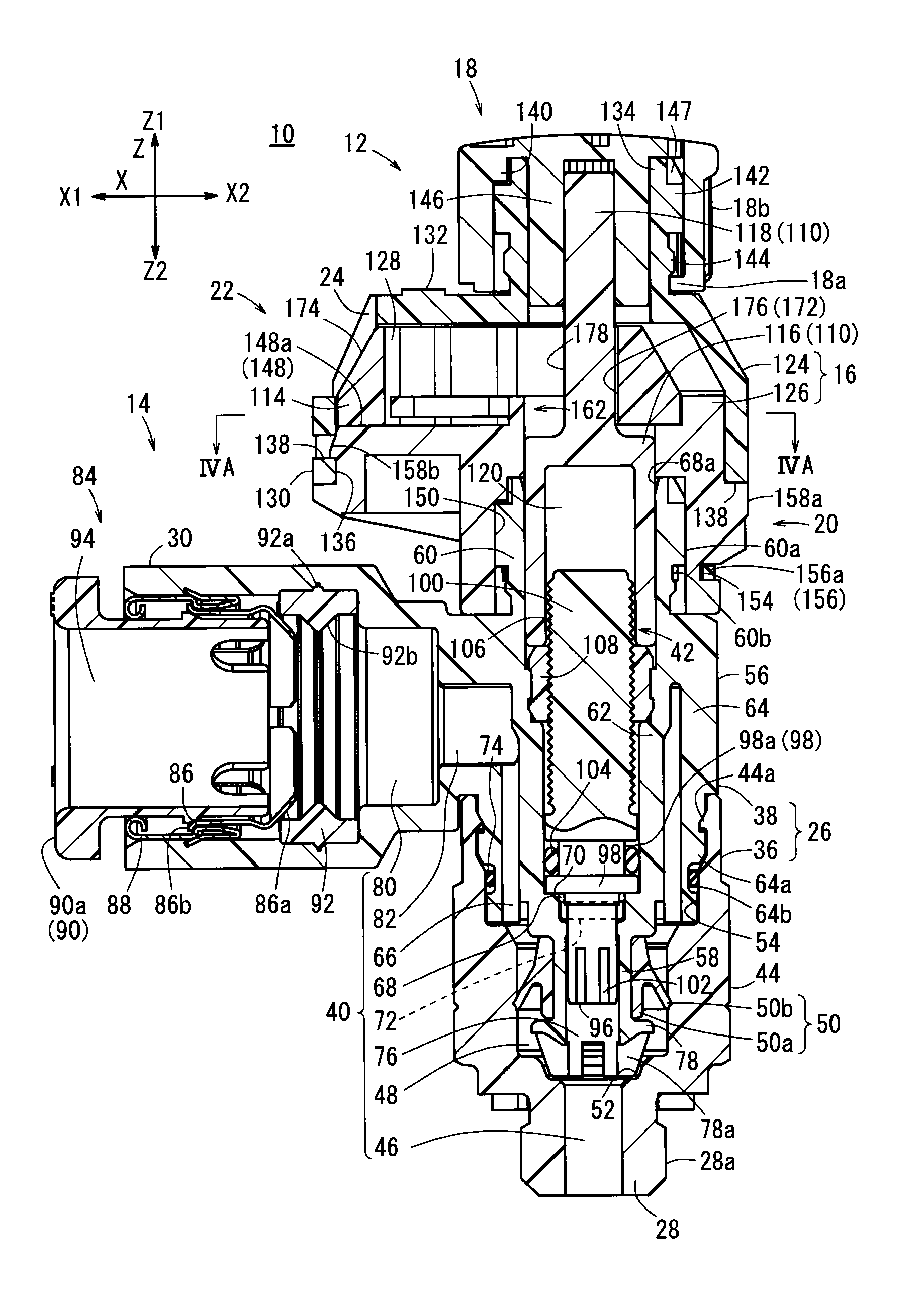
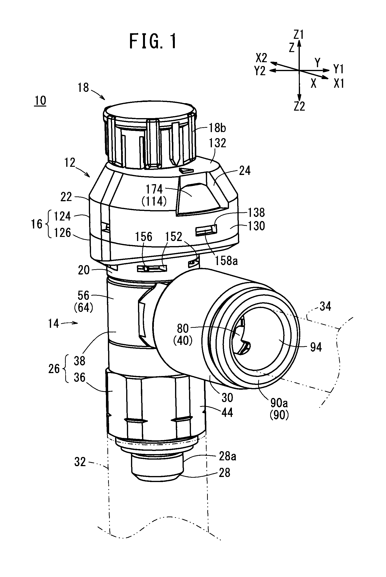
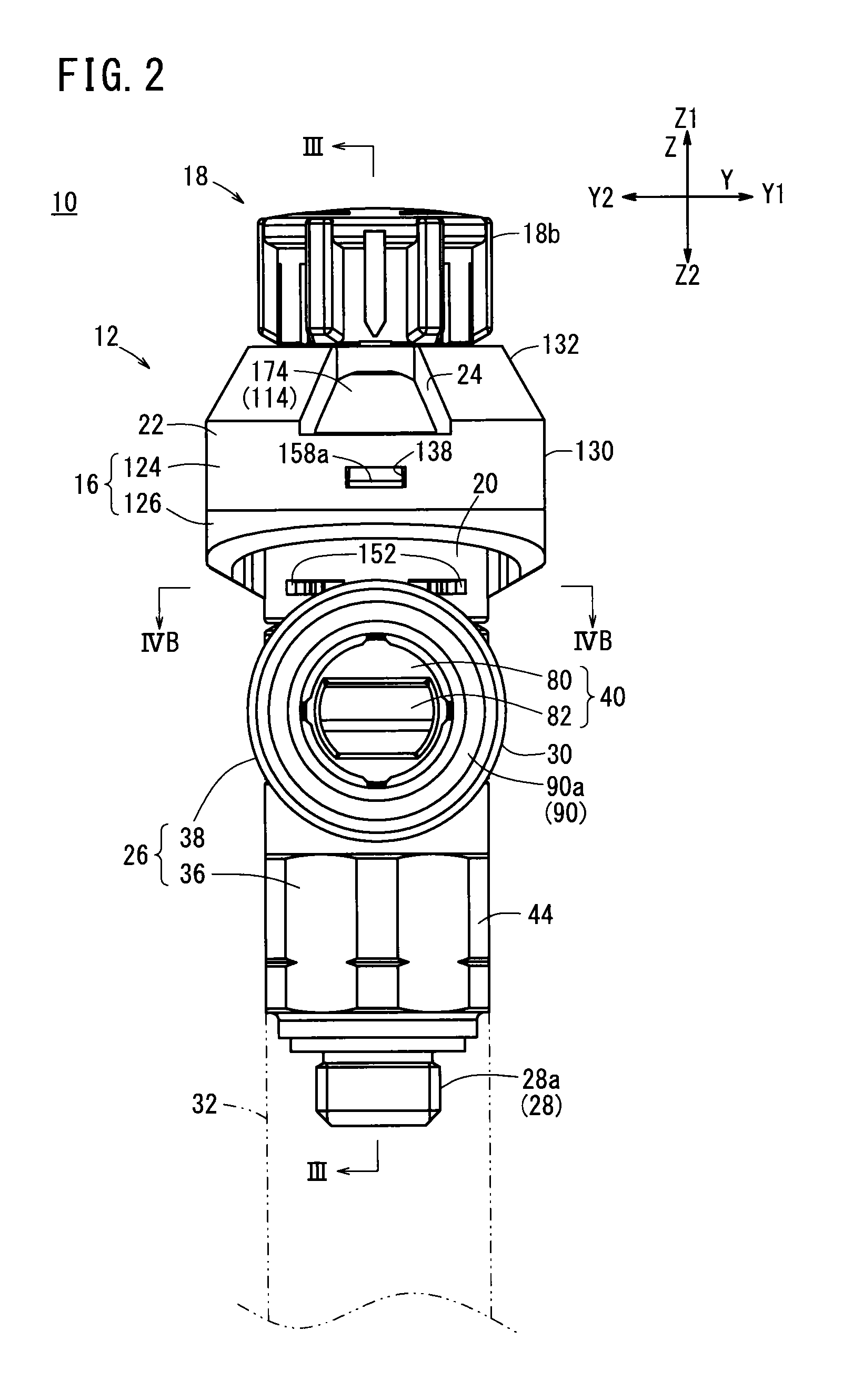
[0038]FIG. 1 is a perspective view showing the overall structure of a flow rate control device 10 according to an embodiment of the present invention, and FIG. 2 is a front view of the flow rate control device 10 of FIG. 1. In the following descriptions, based on the arrow directions shown in FIG. 1, the forward and rearward directions of the flow rate control device 10 are also referred to as X direction (the forward direction is the X1 direction, the rearward direction is the X2 direction), the left and right directions thereof, i.e., widthwise directions, are also referred to as Y direction (the right direction is the Y1 direction, the left direction is the Y2 direction), and the heightwise directions thereof are also referred to as Z direction (the upward direction is the Z1 direction, the downward direction ...


PUM


Abstract

A flow rate control device is provided with a flow rate adjustment indication device for operating the displacement of a needle valve relative to a flow passage. The flow rate adjustment indication device is provided with a housing, a rotation transmission member which displaces the needle valve by rotational operation, and an annularly shaped indication ring which has a hole through which the rotation transmission member is inserted. The indication ring has graduations which indicate a change in the flow rate of liquid. The engagement of the engagement section of the needle valve displaces the indication ring in the circumferential direction and changes the position of the graduations.

Description

TECHNICAL FIELD[0001]The present invention relates to a flow rate control device in which the flow rate of a fluid that flows through the interior thereof is controlled, while indicating a change in the flow rate of the fluid caused by an operation of a user.BACKGROUND ART[0002]In a pipe through which a fluid such as a gas or a liquid flows, a flow rate control device for controlling the flow rate of the fluid is arranged. For example, as disclosed in Japanese Laid-Open Patent Publication No. 2011-043196, a flow rate control device (flow rate control valve) includes a flow passage disposed in the interior of a valve housing to which a pipe is connected, and the flow passage is opened and closed by a needle valve element. The flow rate of the fluid that flows through the flow passage is controlled by the degree of opening of the needle valve element.[0003]Further, the flow rate control device includes, as a structure for operating the displacement (movement) of the needle valve eleme...

Claims


Application Information

Patent Timeline
Patent Type & Authority Patents(United States)
IPC IPC(8): F16K37/00F16K31/50F16K1/04F16K3/24
CPCF16K37/0016F16K1/04F16K3/246F16K31/508Y10T137/8275F16K3/24F16K37/00F16K37/0008
Inventor SHISHIDO, KENJI
Owner SMC CORP
Why Eureka
Try Eureka