Battery control system and battery pack

a battery control system and control system technology, applied in secondary cell servicing/maintenance, safety/protection circuits, instruments, etc., can solve the problems of unplanned balance control and battery control unit not performing unnecessary balance control, and achieve unplanned balance control and stably charge or discharge the battery pack

Active Publication Date: 2016-12-20
ENVISION AESC ENERGY DEVICES LTD
View PDF9 Cites 10 Cited by
  • Summary
  • Abstract
  • Description
  • Claims
  • Application Information

AI Technical Summary

Benefits of technology

[0011]According to the present invention, the battery control unit performs the balance control for reducing the voltage difference between at least two battery units, on the basis of the voltages measured by the voltage measurement unit, when the first temperature condition in which the temperature difference between the highest temperature unit and the lowest temperature unit is equal to or greater than a reference value is not satisfied. On the other hand, when the temperature difference satisfies the first temperature condition, the battery control unit does not perform the balance control. Thereby, when the cause for the occurrence of the voltage difference between each of the battery units is a temperature difference between each of the battery units, it is possible for the balance control not to be performed. That is, when the residual capacities of the respective battery units are equal to each other, unnecessary balance control is not performed. Therefore, it is possible to stably charge or discharge the battery pack while appropriately determining the cause for the occurrence of the voltage difference between each of the battery units.

Problems solved by technology

On the other hand, when the temperature difference satisfies the first temperature condition, the battery control unit does not perform the balance control.
That is, when the residual capacities of the respective battery units are equal to each other, unnecessary balance control is not performed.

Method used


Image

  • Battery control system and battery pack
  • Battery control system and battery pack
  • Battery control system and battery pack

Examples


first embodiment

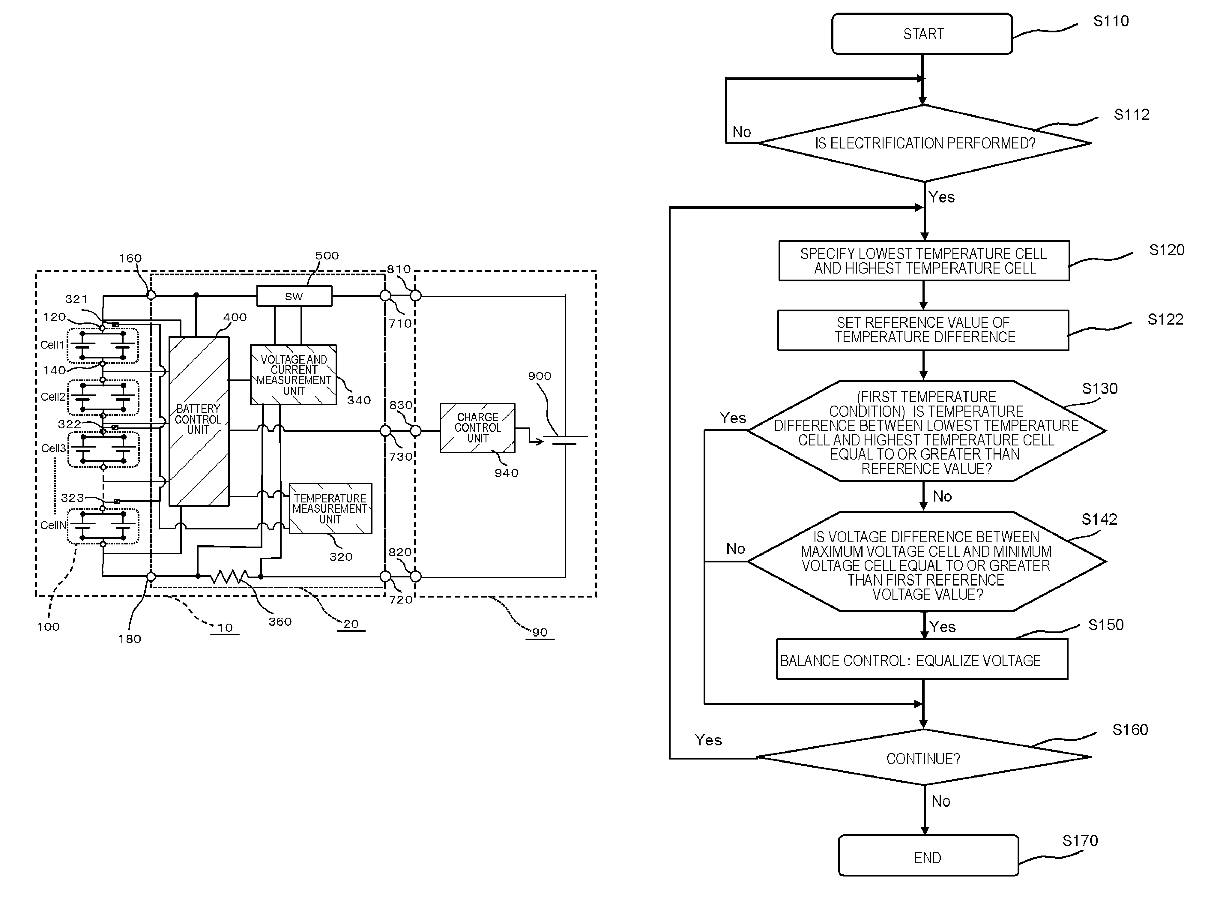
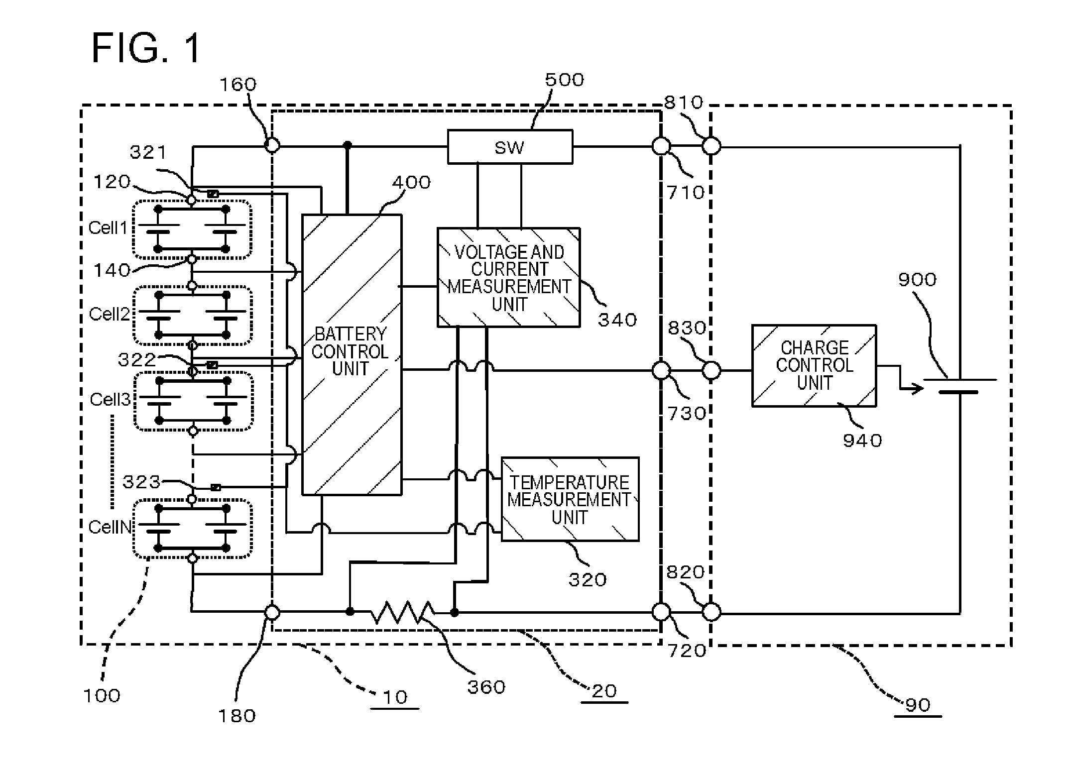
[0032]The battery pack 10 according to a first embodiment will be described with reference to FIGS. 1 and 2. FIG. 1 is a circuit diagram illustrating a configuration of the battery pack 10 and an electronic device 60 according to the first embodiment. The battery pack 10 includes a plurality of battery cells 100, a temperature measurement unit (temperature measurement unit 320 and temperature sensor), a voltage measurement unit and an electrification detection unit (voltage and current measurement unit 340), and a battery control unit (battery control unit 400). Meanwhile, in the first embodiment, the voltage and current measurement unit 340 serves both as the voltage measurement unit and the electrification detection unit. The plurality of battery cells 100 are connected in series to each other. The temperature measurement unit 320 measures temperatures of two or more battery cells 100. The battery control unit 400 controls charge and discharge of the battery cell 100. In addition,...

modified example

[0135]The first embodiment can be modified as follows. In the following modified example, the same effects as that in the first embodiment are also obtained.

[0136]In the first embodiment, a case where the battery cell 100 having a maximum voltage is a lowest temperature cell has been described. However, the battery cell 100 having a maximum voltage may not be a lowest temperature cell. In this case, it is also possible to obtain the same effect as that in the first embodiment. Meanwhile, in this case, the battery cell 100 of which the voltage becomes maximum is targeted for determination in S142.

[0137]In addition, in the first embodiment, a case has been described in which it is determined in S142 whether the voltage difference is equal to or greater than the first reference voltage value. However, as shown in FIG. 4, instead of S142, the battery control unit 400 may determine whether there is a battery cell 100 in which a difference between the voltage thereof and an average voltag...

second embodiment

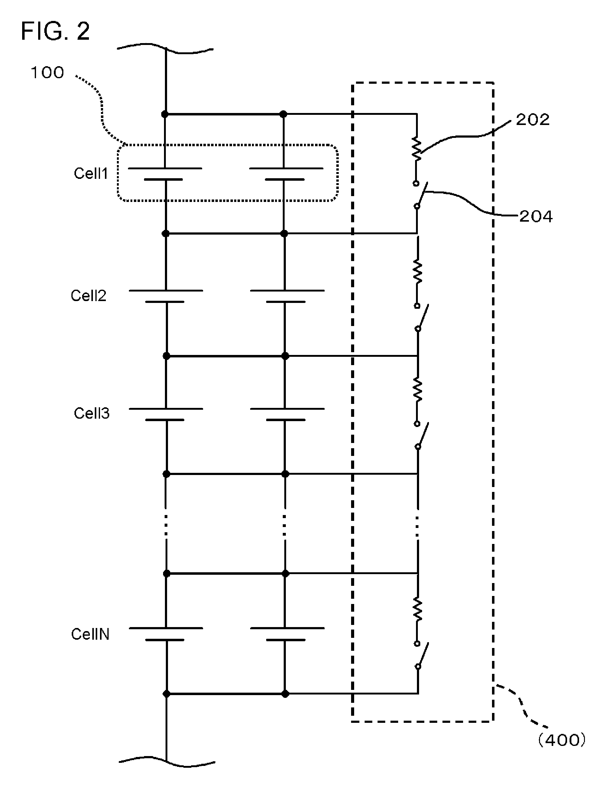
[0144]A second embodiment will be described with reference to FIGS. 8 and 9. FIG. 8 is a circuit diagram illustrating a configuration of a battery pack 10 according to the second embodiment. FIG. 9 is an equivalent circuit diagram in the vicinity of the battery cells 100 of the battery pack 10 according to the second embodiment. The second embodiment is the same as the first embodiment, except for the following points. The battery pack 10 of the second embodiment further includes a balance circuit 200 that adjusts the voltages of the battery cells 100. In addition, the battery control unit 400 performs balance control by controlling the balance circuit 200. Hereinafter, a detailed description will be given.

[0145]In the second embodiment, the balance circuit 200 which is a unit that adjusts the voltage of each of the battery cells 100 in the battery control unit 400 according to the first embodiment is provided independently.

[0146]As shown in FIG. 8, the balance circuit 200 is connec...


PUM

PropertyMeasurementUnit
temperatureaaaaaaaaaa
temperaturesaaaaaaaaaa
voltage measurementaaaaaaaaaa

Abstract

A battery control unit (400) controls charge and discharge of battery cells (100) on the basis of temperatures measured by a temperature measurement unit (320) and voltages measured by the voltage and current measurement unit (340). In addition, the battery control unit (400) specifies a lowest temperature cell having the lowest temperature and a highest temperature cell having the highest temperature on the basis of the temperatures measured by the temperature measurement unit (320), when a current is greater than 0. In addition, the battery control unit (400) performs balance control for equalizing voltages of all the battery cells (100), on the basis of the voltages measured by the voltage and current measurement unit (340), when a first temperature condition in which a temperature difference ΔT between the highest temperature cell and the lowest temperature cell is equal to or greater than a reference value T1 is not satisfied. On the other hand, when the temperature difference ΔT satisfies the first temperature condition, the battery control unit (400) does not perform the balance control.

Description

CROSS REFERENCE TO RELATED APPLICATIONS[0001]This application is a National Stage of International Application No. PCT / JP2013 / 000709, filed Feb. 8, 2013, claiming priority from Japanese Patent Application No. 2012-044631, filed Feb. 29, 2012, the contents of all of which are incorporated herein by reference in their entirety.TECHNICAL FIELD[0002]The present invention relates to a battery control system and a battery pack.BACKGROUND ART[0003]Various charge and discharge methods and control circuits are proposed in order to stably obtain power from a battery pack.[0004]Patent Document 1 (Japanese Unexamined Patent Publication No. 2009-232559) discloses a battery pack charge balance circuit as described below. Such a battery pack charge balance circuit includes a first balance control circuit, a second balance control circuit and a protection circuit. The first balance control circuit and the second balance control circuit are connected in series to each other between both charge and d...

Claims


Application Information

Patent Timeline
Patent Type & Authority Patents(United States)
IPC IPC(8): H02J7/04H02J7/00H02J7/16H01M10/42H01M10/48G01R31/36
CPCH02J7/0014G01R31/3606H01M10/425H01M10/482H01M10/486H02J7/007H02J7/0016H02J7/0021H02J7/0026H02J7/0091H01M2010/4271Y02E60/10H02J7/00302H02J7/0047H02J7/00306H02J7/007194G01R31/382
Inventor YOSHIDA, TADAHIRO
Owner ENVISION AESC ENERGY DEVICES LTD
Why Eureka
Try Eureka