
Power safety inspection system based on wearable device

A power security and inspection system technology, applied in location-based services, specific environment-based services, transmission systems, etc., can solve the problem that the safety of inspection personnel cannot be guaranteed, and the inspection efficiency of power equipment or lines is low. problems, to achieve the effect of shortening the rescue time, improving the inspection efficiency and improving the rescue efficiency

Inactive Publication Date: 2019-10-18
STATE GRID ZHEJIANG ELECTRIC POWER CO LTD JIAXING POWER SUPPLY CO
View PDF14 Cites 1 Cited by
  • Summary
  • Abstract
  • Description
  • Claims
  • Application Information

AI Technical Summary

Problems solved by technology

[0003] The purpose of the present invention is to solve the problems of low efficiency of power equipment or line inspection and the safety of inspection personnel cannot be guaranteed. A power safety inspection system based on wearable devices is designed. The helmet is used as a protective tool and a communication tool. It can guarantee the life safety of inspection personnel, and at the same time transmit the on-site data to the remote terminal in time. The remote monitoring terminal is used for centralized management of data, fault warning and centralized management of operators. According to the inspection line equipment information, the inspection strategy is formulated , reduce the labor intensity of inspection personnel and improve inspection efficiency

Method used


Image

  • Power safety inspection system based on wearable device

Examples


Embodiment

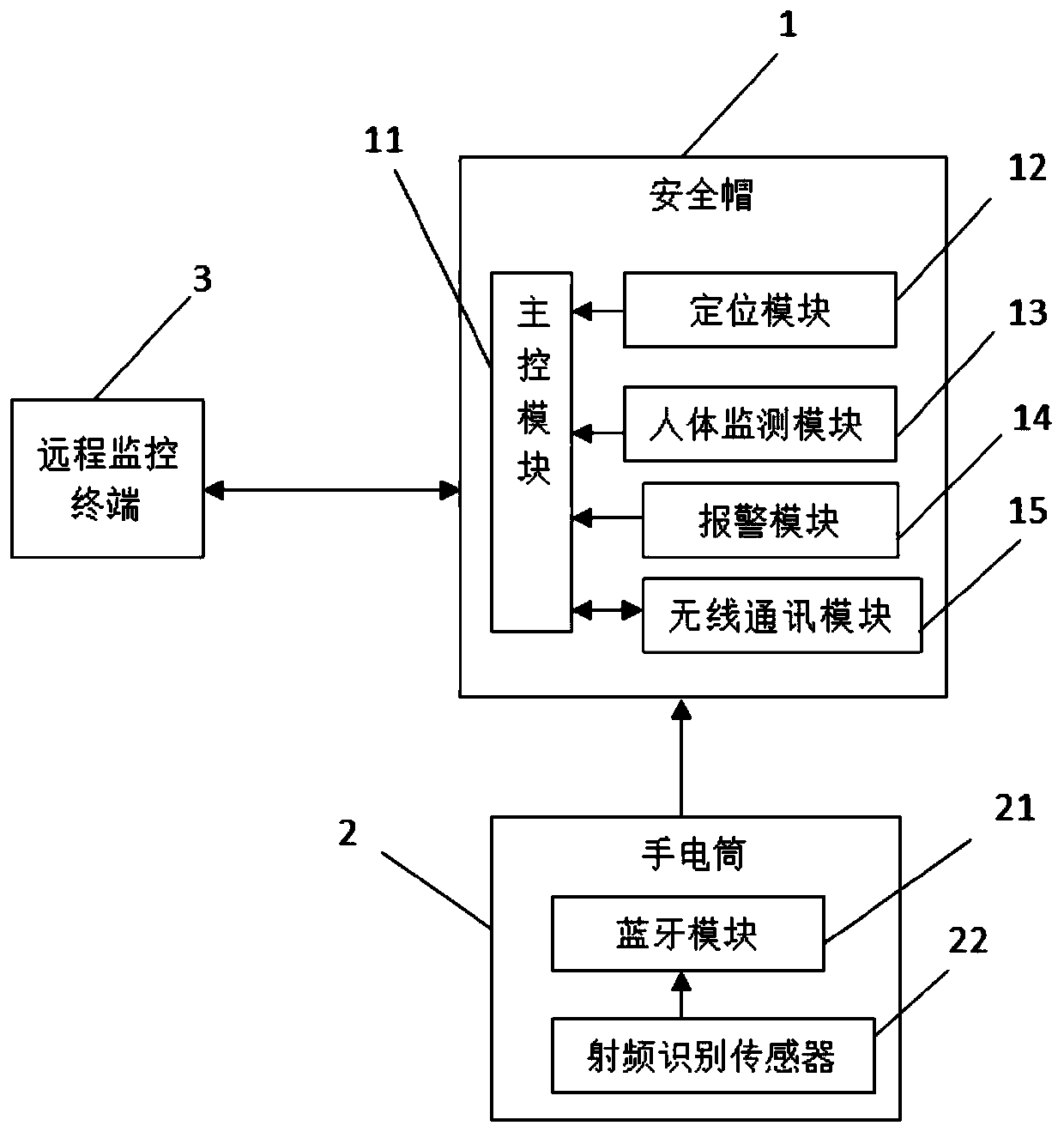
[0022] Example: as figure 1 Shown is a structural block diagram of a wearable device-based power safety inspection system of the present invention, which consists of a remote monitoring terminal 3, a safety helmet 1, and a flashlight 2. The rear end of the safety helmet 1 is reserved with a control chamber , a power supply, a main control module 11, an alarm module 14, a positioning module 12, a human body detection module and a wireless communication module 15 are installed in the control chamber; the main control module 11 adopts an AT89C51 single-chip microcomputer, and the lithium battery provides power to the single-chip microcomputer, and the alarm module 14 It is composed of an alarm and a proximity sensor. The alarm receives the alarm information and will emit a pleasant alarm sound and the alarm light flashes. The positioning module 12 adopts a GPS positioning sensor to upload the position information of the inspectors in real time; the human body monitoring module 13 ...


PUM


Abstract

The invention discloses a power safety inspection system based on a wearable device. The system comprises a safety helmet, a flashlight and a remote monitoring terminal. The safety helmet includes a helmet body; and a control chamber is arranged at the rear end of the helmet body. A main control module, a positioning module, a human body monitoring module, an alarm module, and a wireless communication module are arranged in the control chamber; the positioning module, the human body monitoring module, the alarm module and the wireless communication module are connected with the main control unit respectively electrically; and the wireless communication module is in communication with the remote monitoring terminal. The safety helmet is used for storage and transmission of the inspection information of electric equipment to guarantee the personal safety of the inspection personnel. The flashlight is used for collecting equipment information and serves as inspection lighting equipment. The remote monitoring terminal is used for realizing centralized management of data, fault warning and centralized management of the operators. According to the inspection line equipment information, an inspection strategy is made, so that the labor intensity of the inspection personnel is reduced and the inspection efficiency is improved.

Description

technical field [0001] The invention relates to the technical field of electric power inspection equipment, in particular, to a power safety inspection system based on wearable devices. Background technique [0002] Power inspection is one of the important operations to ensure the safe operation of the power system. Since the power generation, transmission and distribution links include various electrical equipment and lines, regular inspections are required, and the requirements for inspection personnel are too high. The work intensity is high, and there are potential safety hazards during inspections. The information collected by inspections cannot be managed centrally, resulting in low equipment management efficiency and inability to formulate efficient inspection strategies. SUMMARY OF THE INVENTION [0003] The purpose of the present invention is to design a power safety inspection system based on wearable equipment in view of the low efficiency of power equipment or ...

Claims


Application Information

Patent Timeline
IPC IPC(8): G07C1/20G08B21/02G08B21/04G08B25/08H04L29/08H04W4/02H04W4/38
CPCG07C1/20G08B21/02G08B21/0453G08B25/08H04L67/12H04W4/02H04W4/38H04L67/52Y02D30/70
Inventor 陈冰晶王跃强郭磊
Owner STATE GRID ZHEJIANG ELECTRIC POWER CO LTD JIAXING POWER SUPPLY CO
Learn More