Battery control system and battery pack

Active Publication Date: 2015-02-05
NEC ENERGY DEVICES LTD
View PDF2 Cites 38 Cited by
  • Summary
  • Abstract
  • Description
  • Claims
  • Application Information

AI Technical Summary

Benefits of technology

[0007]The inventor has found that the following problem occurs in a battery pack having a plurality of battery units which are connected in series to each other. In battery units within a battery pack, a temperature difference occurs due to the arrangement of the battery units. In this case, even when residual capacities between each of the battery units are equal to each other, a voltage difference occurs between each of the battery units during electrification. In this case, when control for equalizing voltages between each of the battery units is performed, there is the possibility of the equal residual capacities varying inversely.
[0008]According to the present invention, there is provided a battery control system including: a temperature measurement unit that measures temperatures of two or more battery units of a plurality of battery units which are connected in series to each other; a voltage measurement unit that measures voltages of the battery units; an electrification detection unit that detects electrification of the battery units; and a battery control unit that controls charge and discharge of the battery units, wherein the battery control unit specifies a lowest temperature unit in which the temperature is lowest and a highest temperature unit in which the temperature is highest, on the basis of the temperatures measured by the temperature measurement unit, during the electrification of the battery units, further performs balance control for reducing a difference between the voltages of at least two battery units, on the basis of the voltages measured by the voltage measurement unit, when a first temperature condition in which a temperature difference between the highest temperature unit and the lowest temperature unit is equal to or greater than a reference value is not satisfied, and does not perform the balance control when the temperature difference satisfies the first temperature condition.
[0009]According to the present invention, there is provided a battery pack including: a plurality of battery units which are connected in series to each other; a temperature measurement unit that measures temperatures of the two or more battery units;

Problems solved by technology

On the other hand, when the temperature difference satisfies the first temperature condition, the battery control unit does not perform the balance

Method used


Image

  • Battery control system and battery pack
  • Battery control system and battery pack
  • Battery control system and battery pack

Examples


Example

First Embodiment

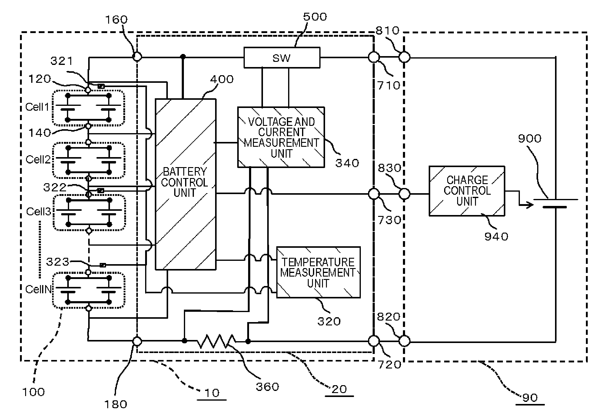
[0031]The battery pack 10 according to a first embodiment will be described with reference to FIGS. 1 and 2. FIG. 1 is a circuit diagram illustrating a configuration of the battery pack 10 and an electronic device 60 according to the first embodiment. The battery pack 10 includes a plurality of battery cells 100, a temperature measurement unit (temperature measurement unit 320 and temperature sensor), a voltage measurement unit and an electrification detection unit (voltage and current measurement unit 340), and a battery control unit (battery control unit 400). Meanwhile, in the first embodiment, the voltage and current measurement unit 340 serves both as the voltage measurement unit and the electrification detection unit. The plurality of battery cells 100 are connected in series to each other. The temperature measurement unit 320 measures temperatures of two or more battery cells 100. The battery control unit 400 controls charge and discharge of the battery cell 1...

Example

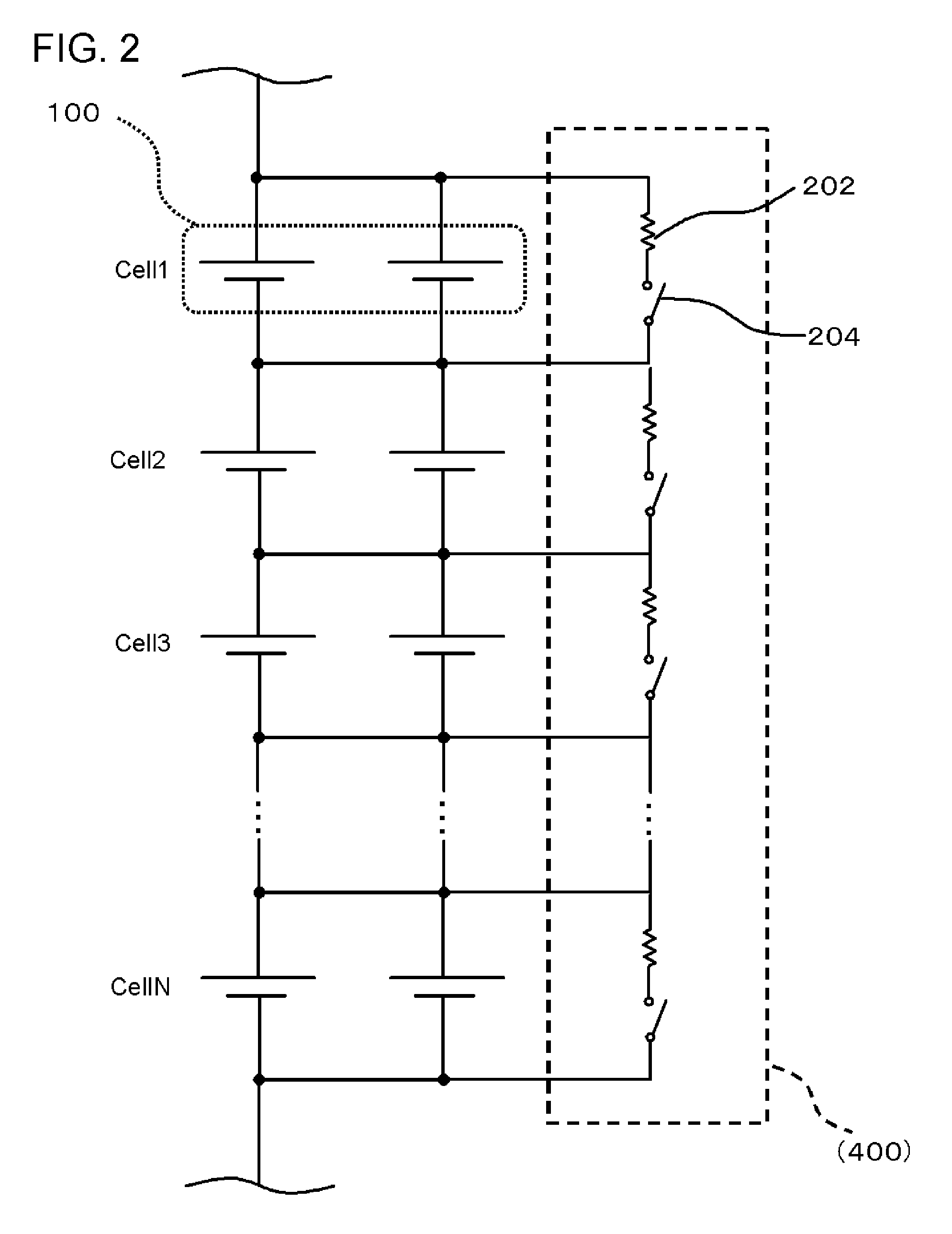
[0143]A second embodiment will be described with reference to FIGS. 8 and 9. FIG. 8 is a circuit diagram illustrating a configuration of a battery pack 10 according to the second embodiment. FIG. 9 is an equivalent circuit diagram in the vicinity of the battery cells 100 of the battery pack 10 according to the second embodiment. The second embodiment is the same as the first embodiment, except for the following points. The battery pack 10 of the second embodiment further includes a balance circuit 200 that adjusts the voltages of the battery cells 100. In addition, the battery control unit 400 performs balance control by controlling the balance circuit 200. Hereinafter, a detailed description will be given.

[0144]In the second embodiment, the balance circuit 200 which is a unit that adjusts the voltage of each of the battery cells 100 in the battery control unit 400 according to the first embodiment is provided independently.

[0145]As shown in FIG. 8, the balance circuit 200 is connec...

Example

Third Embodiment

[0154]FIG. 10 is a flow diagram illustrating a control method according to a third embodiment. The third embodiment is the same as the first embodiment, except for the following points. The battery control unit 400 further specifies a first cell having the highest voltage when the battery cell 100 is charged, on the basis of the voltages measured by the voltage and current measurement unit 340. In addition, the battery control unit 400 does not perform the balance control when the temperature difference ΔT satisfies the first temperature condition, and the lowest temperature cell is the same as the first cell. On the other hand, when the temperature difference ΔT satisfies the first temperature condition, and the lowest temperature cell is different from the first cell, the balance control is performed. Hereinafter, a detailed description will be given. Meanwhile, in the “first cell”, the “battery cell” can be replaced by the “battery unit”, and also be replaced by t...


PUM


Abstract

A battery control unit (400) controls charge and discharge of battery cells (100) on the basis of temperatures measured by a temperature measurement unit (320) and voltages measured by the voltage and current measurement unit (340). In addition, the battery control unit (400) specifies a lowest temperature cell having the lowest temperature and a highest temperature cell having the highest temperature on the basis of the temperatures measured by the temperature measurement unit (320), when a current is greater than 0. In addition, the battery control unit (400) performs balance control for equalizing voltages of all the battery cells (100), on the basis of the voltages measured by the voltage and current measurement unit (340), when a first temperature condition in which a temperature difference ΔT between the highest temperature cell and the lowest temperature cell is equal to or greater than a reference value T1 is not satisfied. On the other hand, when the temperature difference ΔT satisfies the first temperature condition, the battery control unit (400) does not perform the balance control.

Description

TECHNICAL FIELD[0001]The present invention relates to a battery control system and a battery pack.BACKGROUND ART[0002]Various charge and discharge methods and control circuits are proposed in order to stably obtain power from a battery pack.[0003]Patent Document 1 (Japanese Unexamined Patent Publication No. 2009-232559) discloses a battery pack charge balance circuit as described below. Such a battery pack charge balance circuit includes a first balance control circuit, a second balance control circuit and a protection circuit. The first balance control circuit and the second balance control circuit are connected in series to each other between both charge and discharge terminals of a charge and discharge circuit. The first balance control circuit includes a control unit connected in parallel thereto, corresponding to a plurality of battery units. The second balance control circuit includes a first branch and a second branch which are connected in parallel to each other. Thereby, it...

Claims


Application Information

Patent Timeline
IPC IPC(8): H02J7/00G01R31/36
CPCH02J7/0014G01R31/3606H02J7/007H02J7/0021H02J7/0026H02J7/0091H01M10/425H01M10/482H01M10/486H02J7/0016H01M2010/4271Y02E60/10H02J7/00302H02J7/0047H02J7/00306H02J7/007194G01R31/382
Inventor YOSHIDA, TADAHIRO
Owner NEC ENERGY DEVICES LTD
Why Eureka
Try Eureka