Wiring module

a technology of wiring module and wiring module, which is applied in the field of wiring module, can solve the problems affecting the structure, and low degree of freedom, and achieves the effect of increasing the size of the temperature detecting member

Active Publication Date: 2016-12-20
AUTONETWORKS TECH LTD +2
View PDF21 Cites 2 Cited by
  • Summary
  • Abstract
  • Description
  • Claims
  • Application Information

AI Technical Summary

Benefits of technology

[0006]In the temperature sensor having a configuration disclosed in JP 2012-154901A, an operation for attaching the temperature sensor is easy because the temperature sensor is positioned by attaching the resin module to the power storage elements, but there is the problem that the resin module needs to be produced depending on the positions of the power storage elements that serve as temperature detection targets, the number thereof, or the like, resulting in a low degree of freedom.
[0012]According to embodiments of the present application, it is thus possible to hold the temperature detecting member in the state in which its movement is restricted without providing a structure for holding the temperature detecting member for the insulating protector, suppressing, in the wiring module including a temperature detecting member, an increase in size of the temperature detecting member.
[0016]The cover may be provided with a latched section that is latched to the insulating protector. With such a configuration, since the cover is latched to the insulating protector, it is possible to maintain the state in which movement of the temperature detecting member is restricted.
[0017]The connection member holding section may be provided with a positioning section that is obtained by cutting out a part of the connection member holding section, and is configured to receive and position a part of the temperature detecting member. With such a configuration, the temperature detecting member is received and positioned by the cutout section, and thus causing no interference problem between the positioning section and another member.
[0018]According to embodiments of the present application, it is possible to suppress, in a wiring module including a temperature detecting member, an increase in size of the temperature detecting member.

Problems solved by technology

In the temperature sensor having a configuration disclosed in JP 2012-154901A, an operation for attaching the temperature sensor is easy because the temperature sensor is positioned by attaching the resin module to the power storage elements, but there is the problem that the resin module needs to be produced depending on the positions of the power storage elements that serve as temperature detection targets, the number thereof, or the like, resulting in a low degree of freedom.
However, if a structure for holding the temperature detecting member is provided so as not to interfere with a tool for connecting the busbar or the like to an electrode terminal, or the like, the temperature detecting member will need to have a size to be able to be held by the holding structure of the insulating protector, and thus an increase in size of the temperature detecting member will be concerned.
Furthermore, the holding structure of the temperature detecting member may interfere with the structure for holding the busbar or the like.

Method used


Image

  • Wiring module
  • Wiring module
  • Wiring module

Examples


embodiment 1

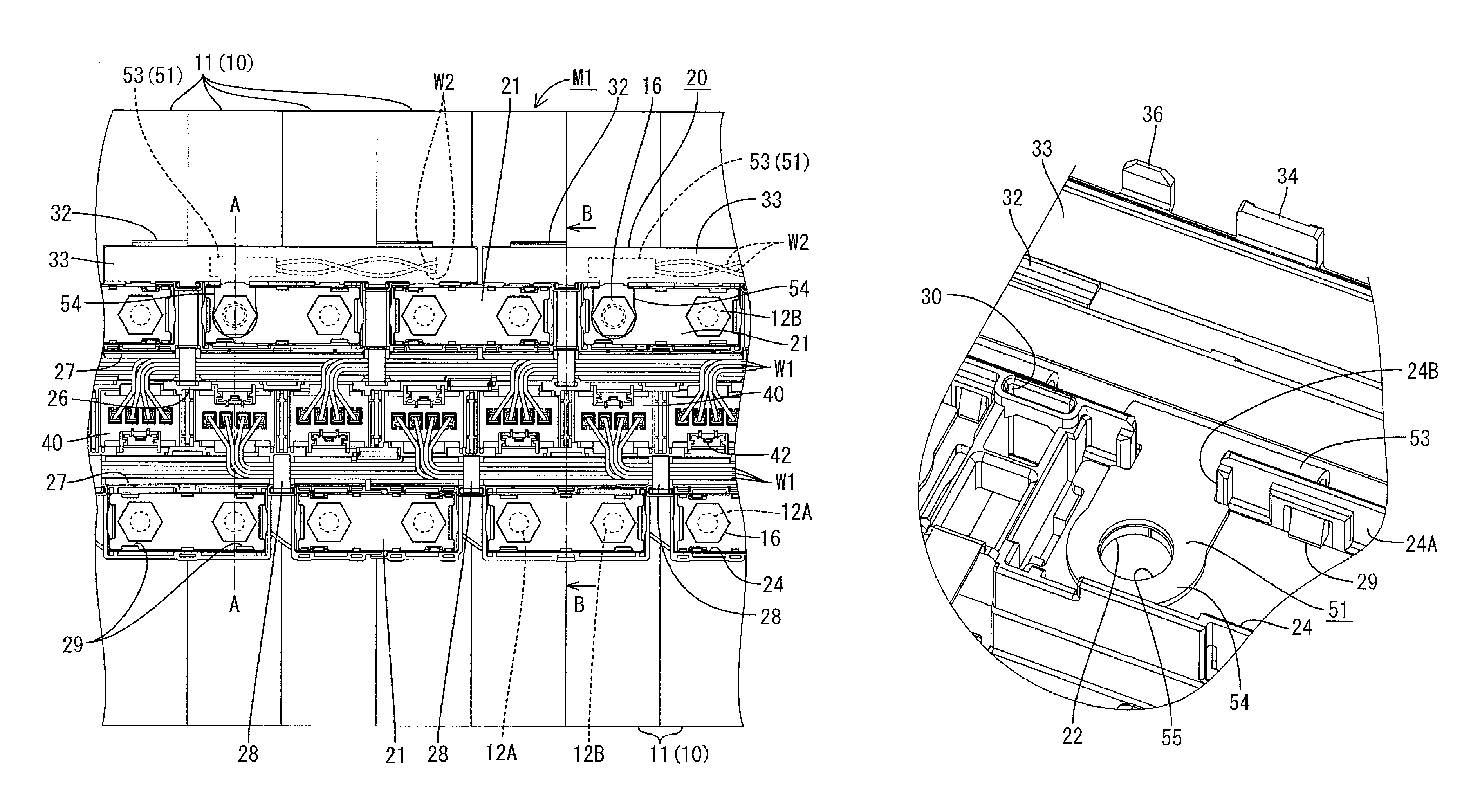
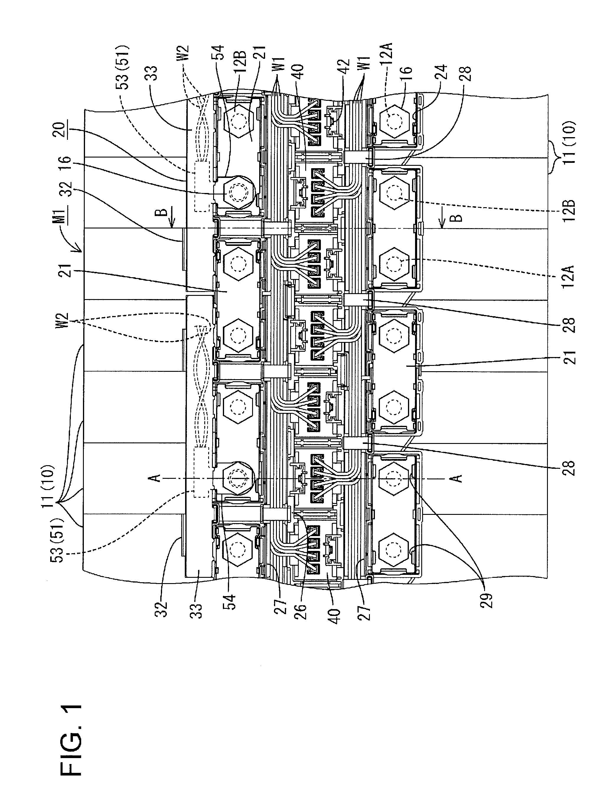
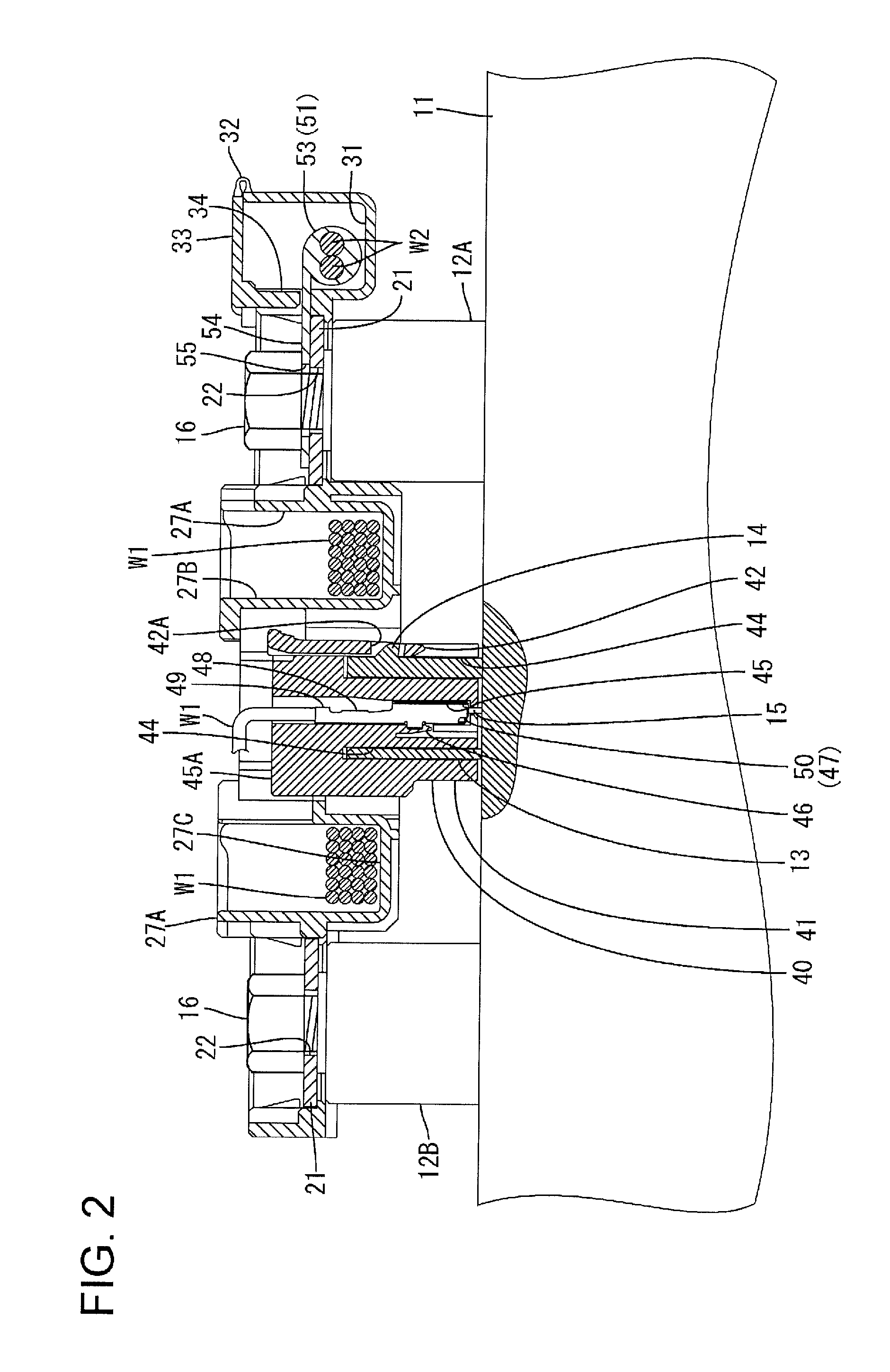
[0030]Embodiment 1 of the present application will be described with reference to FIGS. 1 to 11. A battery module M1 (an example of a power storage module) according to the present embodiment is mounted on a vehicle (not shown) such as an electric car or hybrid car, and is used as an electric power source for driving the vehicle.

[0031]The battery module M1 includes a single cell group 10 (an example of a power storage element group) in which a plurality of cell packs 11 (an example of a power storage element) are lined up, and a wiring module 20 that is attached to the single cell group 10. In the following description, if there are a plurality of the same members, a reference numeral may be given to one member and be omitted for the other members.

Single Cell Group 10

[0032]As shown in FIG. 1, the battery module M1 of the present embodiment includes the single cell group 10 in which a plurality of cell packs 11 are lined up, the plurality of cell packs each including four single cell...


PUM

PropertyMeasurementUnit
temperatureaaaaaaaaaa
degree of freedomaaaaaaaaaa
sizeaaaaaaaaaa

Abstract

A wiring module to be attached to a power storage element group in which a plurality of power storage elements each having positive and negative electrode terminals are lined up includes: an insulating protector having a connection member holding section for holding a connection member that electrically connects adjacent electrode terminals; a temperature detecting member that is arranged so as to be in contact with the connection member held by the connection member holding section and is configured to detect the temperature of the connection member; a cover configured to cover the insulating protector; and a restricting member configured to restrict movement of the temperature detecting member by covering the insulating protector with the cover.

Description

CROSS-REFERENCE TO RELATED APPLICATIONS[0001]This application is a National Stage application of International Application No. PCT / JP2014 / 056114, filed on Mar. 10, 2014, and claims priority to Japanese Patent Application No. 2013-065651 filed on Mar. 27, 2013, the disclosures of both of which are incorporated herein by reference in their entireties.TECHNICAL FIELD[0002]Embodiments of the present application relate to a wiring module.BACKGROUND[0003]In power storage modules such as electric cars or hybrid cars, a large number of power storage elements are lined up laterally and connected to each other in order to increase an output. The power storage elements are configured to be connected in series or in parallel to each other by adjacent electrode terminals being connected by connection members such as busbars.[0004]If such a power storage module is used in a high temperature condition, the lifetime thereof may be decreased, and a power storage module in which a plurality of lithiu...

Claims


Application Information

Patent Timeline
Patent Type & Authority Patents(United States)
IPC IPC(8): H05K7/00H01M10/615H01M10/625H01M10/48H01M2/20H01M10/65H01M10/613H01M10/6553H01M50/51H01M50/517
CPCH05K7/005H01M2/206H01M10/486H01M10/613H01M10/615H01M10/625H01M10/65H01M10/6553H01M2220/20Y02E60/10H01M50/51H01M50/517
Inventor NAKAYAMA, OSAMUMORITA, MITSUTOSHITAKADA, KOTAROFUKUSHIMA, NAOKI
Owner AUTONETWORKS TECH LTD
Why Eureka
Try Eureka