
Intraluminal polymeric devices for the treatment of aneurysms

a polymeric device and aneurysm technology, applied in the field of polymeric devices, can solve the problems of repeated leakage into the aneurysmal sac (endoleak), device dislocation from its intended position, and major problems, and achieve the effect of increasing decreasing the stiffness of the polymeric system

Inactive Publication Date: 2016-12-27
YISSUM RES DEV CO OF THE HEBREWUNIVERSITY OF JERUSALEM LTD
View PDF16 Cites 27 Cited by
  • Summary
  • Abstract
  • Description
  • Claims
  • Application Information

AI Technical Summary

Benefits of technology

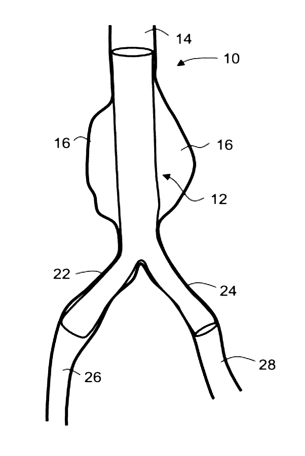
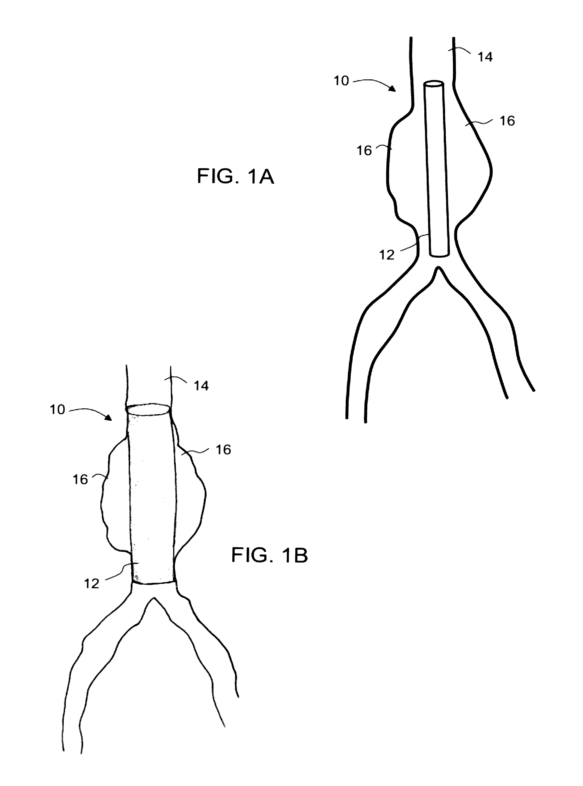
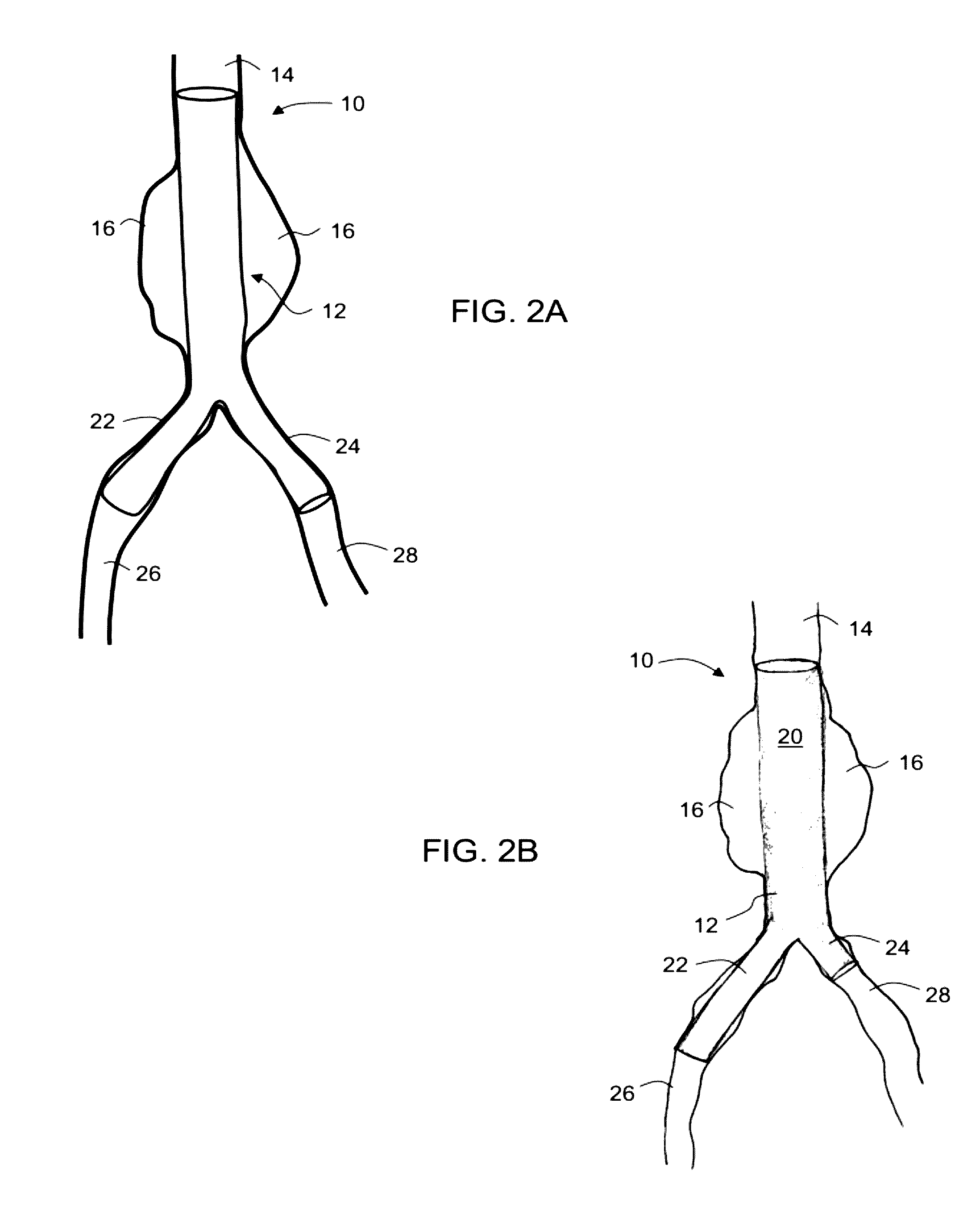
[0018]Embodiments of the present invention therefore relate to forming an isolating tubular structure that is deployed intraluminally at the aneruysmal site and then expanded, so that it tightly attaches to the vessel, proximally and distally to the aneurysm. The device described herein achieves two objectives: (a) isolating the weak aneurysmal arterial wall from the aortic blood stream, thereby immediately minimizing the risk of life-threatening hemorrhage due to sudden rupture; and (b) restoring the artery's luminal cylindrical geometry, distorted by the aneurysmal expansion. The snug and secure attachment of the device to the normal aortic lumen prevents its dislodgment from its position and avoids the occurrence of endoleaks.
[0086]According to some embodiments of the invention, the method further comprises, prior to the expansion of the device in situ, decreasing a stiffness of the polymeric system.

Problems solved by technology

The formation of aneurysms is a life-threatening degenerative pathology of arterial tissues whereby the wall of the artery weakens locally and markedly expands, creating a sac, which can potentially rupture.
These grafts have been widely implanted for several decades with good results, but have all the drawbacks associated with invasive surgical procedures.
However, various factors restrict the use of EVAR.
For example, if the diameter of the proximal vessel is too large, the device may dislodge from its intended position.
In addition, renewed leakage into the aneurysmal sac (endoleak) is a major problem.
The different types of endoleaks can result in the burst of the aneurysm despite the presence of the graft, and approximately 50% of such ruptures lead to the death of the patient.
In addition, the stent / graft device used in EVAR is quite expensive, and may cost approximately 12,000 $.

Method used


Image

  • Intraluminal polymeric devices for the treatment of aneurysms
  • Intraluminal polymeric devices for the treatment of aneurysms
  • Intraluminal polymeric devices for the treatment of aneurysms

Examples


example 1

Polymer Syntheses

[0464]Polycaprolactone Polyurethane (CLUR)

[0465]Polycaprolactone polyurethane co-polymers are generally prepared by co-polymerizing a polycaprolactone-based polymer with hexamethylene diisocyanate, following the exemplary procedures described hereinafter. The polycaprolactone chain is terminated with functional groups that will allow it to react with the diisocyanate, for example, hydroxy, amine, thiol or carboxylic acid groups.

[0466]The polycaprolactone-based polymers PCL2000, PCL1250 and PCL530 were copolymerized with hexamethylene diisocyanate (HDI) to obtain copolymers referred to herein as CLUR (caprolactone urethane) polymers.

[0467]As an example, the synthesis of CLUR2000 from PCL2000 and HDI is depicted schematically in FIG. 10 and described in detail as follows.

[0468]50.0 grams of OH-terminated PCL2000 was dried at 120° C. under a vacuum for 2 hours with magnetic stirring. Hexamethylene diisocyanate and stannous 2-ethyl hexanoate were added to the reaction m...

example 2

Preparation of Devices

[0494]The following describes exemplary methodologies used for preparing a device according some embodiments of the invention.

[0495]Dip Coating:

[0496]Devices were prepared by dip coating on a suitable mold, typically a cylindrical (6-10 mm diameter) polytetrafluoroethylene-coated mandrel, by slowly dipping the mold into a container containing a solution of 15-20% (w / w) polymer in chloroform, and then slowly withdrawing the mold.

[0497]Dipping and withdrawing the mold was performed at a constant velocity in order to obtain a uniform coating. An electronic motor was used to control the vertical movement and speed during the dipping and withdrawing of the mold. The polytetrafluoroethylene-coated mandrel was dipped 7 cm into the polymer solution using a cross head speed (CHS) of 10 mm per minute.

[0498]For the formation of devices with a wall thickness of 300-700 μm, 5 to 10 dipping cycles were preformed, and the polytetrafluoroethylene-coated mandrel was then dried ...

example 3

Expanded Devices

[0508]Tubular structures prepared from CLUR2000 using the air spray technique described in Example 2 were expanded by inserting a balloon into the tubular device and inflating the balloon with warm (50° C.) water.

[0509]Due to the shape of the balloon, the tubular structures were expanded primarily in their middle. The less expanded edges of the tubular structures were cut off in order to better observe the expanded middle sections.

[0510]As shown in FIG. 16, the diameter of the tubular CLUR2000 structures could be increased considerably by expansion.

[0511]Additional air-sprayed CLUR2000 tubular structures were expanded as described above using a balloon which expanded the full length of the tubular structures. The dimensional changes of tubular structures as a result of expansion were then measured and are given in Table 3.

[0512]

TABLE 3Dimensional changes of tubular structures as a result of expansionDimensionBefore expansionAfter expansionChangeLength (cm)7.57.5 +0%I...


PUM

PropertyMeasurementUnit
melting pointaaaaaaaaaa
temperatureaaaaaaaaaa

Abstract

Novel medical devices and uses thereof for lining a blood vessel and / or treating an aneurysm are disclosed herein. The device comprises a non-metallic expandable tubular structure, implantable in a body vessel and being made, at least in part, from a polymeric system characterized by a stiffness which changes upon stimulation under physiological conditions. Novel polymeric systems are further disclosed herein, which are configured to produce a polymeric material upon stimulation under physiological conditions, such that a stiffness of said polymeric material is higher than a stiffness of said system. Uses of polymer systems in the manufacture of a device are further disclosed.

Description

RELATED APPLICATIONS[0001]This application is a National Phase of PCT Patent Application No. PCT / IL2010 / 000562 having International filing date of Jul. 13, 2010, which claims the benefit of priority under 35 USC §119(e) of U.S. Provisional Patent Application No. 61 / 225,063 filed on Jul. 13, 2009. The contents of the above applications are all incorporated herein by reference as if fully set forth herein.FIELD AND BACKGROUND OF THE INVENTION[0002]The present invention, in some embodiments thereof, relates to a polymeric device, and more particularly, but not exclusively, to a polymeric device useful for the treatment of an aneurysm and to polymeric systems useful for forming such a device.[0003]The formation of aneurysms is a life-threatening degenerative pathology of arterial tissues whereby the wall of the artery weakens locally and markedly expands, creating a sac, which can potentially rupture. The expanded arterial sections are considered aneurysms of clinical relevance when the...

Claims


Application Information

Patent Timeline
Patent Type & Authority Patents(United States)
IPC IPC(8): A61M29/04A61L31/06A61F2/945
CPCA61L31/06A61F2/945C08L67/04
Inventor COHN, DANIELPELLED, ITAIABBAS, RANDAMALAL, RAM
Owner YISSUM RES DEV CO OF THE HEBREWUNIVERSITY OF JERUSALEM LTD
Learn More