Abnormality detection device

a detection device and abnormality technology, applied in the direction of secondary cell servicing/maintenance, battery/fuel cell control arrangement, instruments, etc., can solve the problem of complex configuration of devices, and achieve the effect of avoiding overvoltag

Active Publication Date: 2016-12-27
HONDA MOTOR CO LTD
View PDF16 Cites 0 Cited by
  • Summary
  • Abstract
  • Description
  • Claims
  • Application Information

AI Technical Summary

Benefits of technology

[0013]According to the abnormality detection device related to the aspect disclosed in the above (1), for example, in a case where there are a plurality of detection targets of the temperature detection unit, and it is detected whether or not an abnormality has occurred in any one of the plurality of detection targets, it is possible to detect whether or not an abnormality has occurred only with a connection line connected to the resistance detection unit without needing to connect the connection line to the plurality of detection targets. Accordingly, it is possible to prevent a device configuration from being complex.
[0016]Furthermore, in a case of the above (4), it is possible to eliminate an overvoltage when an overvoltage of the storage battery occurs, and also it is possible to detect whether either a short circuit controlled by the short-circuit unit or a short circuit due to an abnormality which does not follow control of the short-circuit unit occurs, by detecting whether or not a short circuit of the resistor section is removed in accordance with a reduction in a voltage of the storage battery.

Problems solved by technology

In the vehicle power source device according to the related art, in a case where the main power source or the subsidiary power source is battery modules formed by a plurality of battery cells, there is a concern that a plurality of monitor lines connected to each battery module may be necessary in order to monitor a voltage of each battery module, and thus a device configuration may be complex.

Method used


Image

  • Abnormality detection device
  • Abnormality detection device
  • Abnormality detection device

Examples


Embodiment Construction

[0019]Hereinafter, an abnormality detection device according to an embodiment of the present invention will be described with reference to the accompanying drawings.

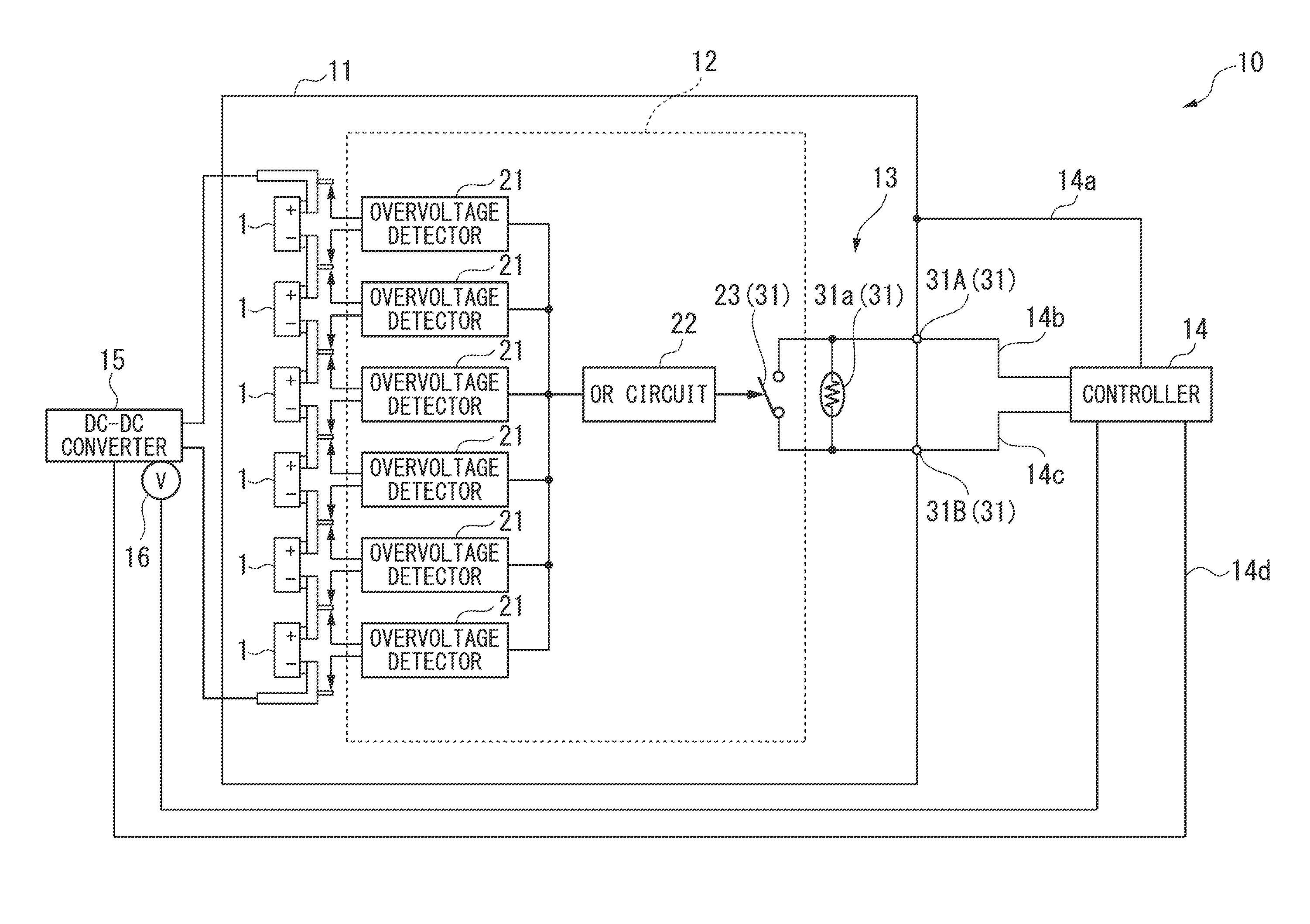
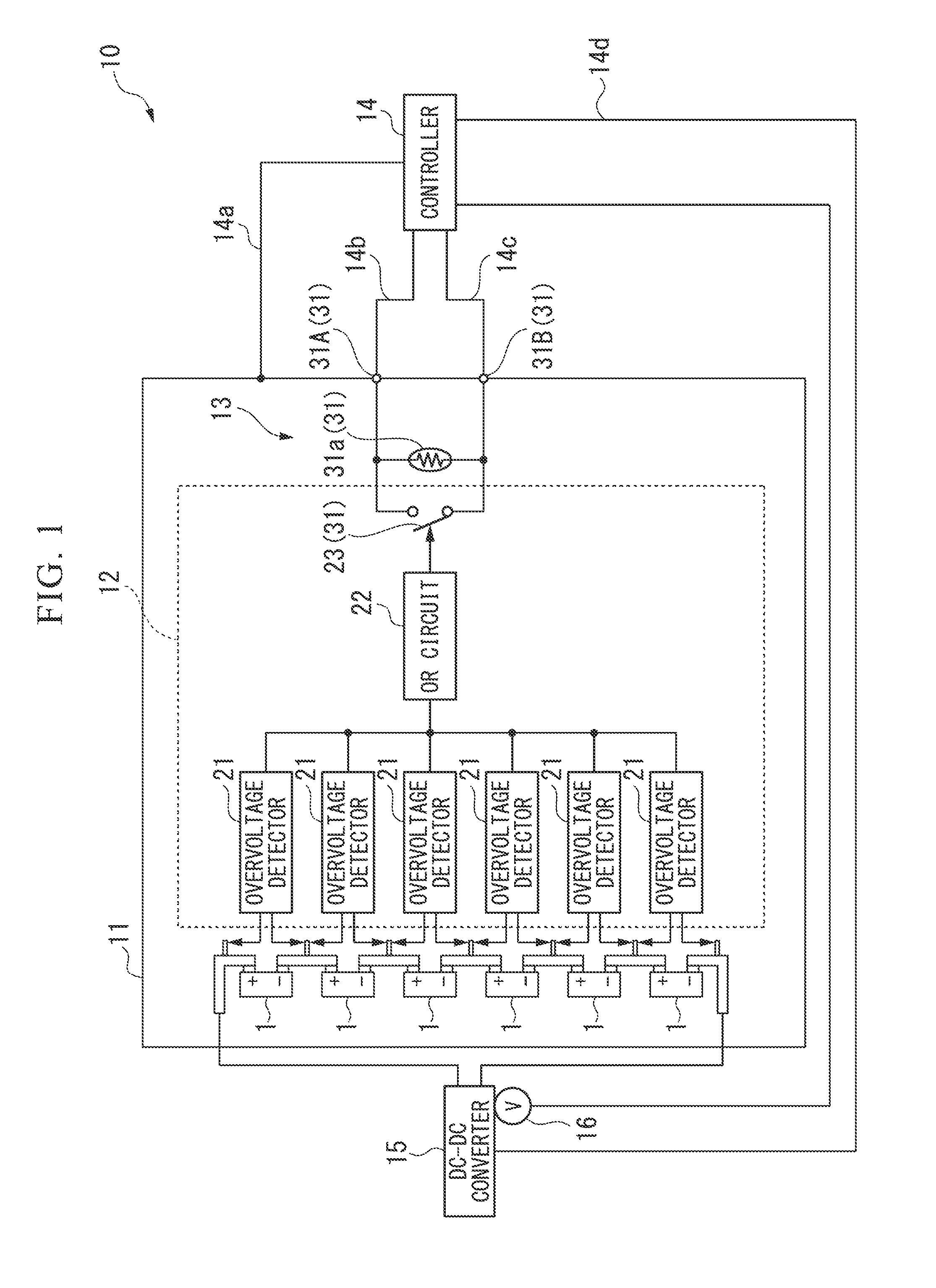
[0020]An abnormality detection device 10 according to the present embodiment can detect whether or not at least one of a plurality of capacitor cells 1 outputs an overvoltage as an abnormality of a capacitor 11 (capacitor module, storage battery) formed by the plurality of capacitor cells 1 which are connected in series to each other, for example, as illustrated in FIG. 1.

[0021]The abnormality detection device 10 includes, for example, an abnormality detection unit 12, a temperature detection unit 13, and a controller (resistance detection unit) 14. The abnormality detection unit 12 includes a plurality of overvoltage detectors 21 provided at the plurality of respective capacitor cells 1, an OR circuit (a short-circuit unit, a voltage control unit) 22 connected to the plurality of overvoltage detectors 21, and a short-ci...


PUM

PropertyMeasurementUnit
resistanceaaaaaaaaaa
temperatureaaaaaaaaaa
resistance valueaaaaaaaaaa

Abstract

An abnormality detection device includes a temperature detection unit that has a resistor section which varies a resistance value depending on a temperature, a resistance detection unit that detects a resistance value of the resistor section, and a short-circuit unit that short-circuits the resistor section, in which the short-circuit unit short-circuits the resistor section when a predetermined abnormality occurs in a detection target of the temperature detection unit.

Description

CROSS-REFERENCE TO RELATED APPLICATION[0001]Priority is claimed on Japanese Patent Application No. 2013-140165, filed on Jul. 3, 2013, the content of which is incorporated herein by reference.BACKGROUND[0002]Field of the Invention[0003]The present invention relates to an abnormality detection device.[0004]Description of Related Art[0005]In the related art, a vehicle power source device is known in which a DC-DC converter is connected between a main power source connected to an electrical load and a subsidiary power source connected to a generator, and a switch is provided between the main power source and the subsidiary power source (for example, refer to Japanese Unexamined Patent Application, First Publication No. 2010-195336).SUMMARY[0006]In the vehicle power source device according to the related art, in a case where the main power source or the subsidiary power source is battery modules formed by a plurality of battery cells, there is a concern that a plurality of monitor lines...

Claims


Application Information

Patent Timeline
Patent Type & Authority Patents(United States)
IPC IPC(8): H02H9/04H01M10/48H01M10/42B60L11/18G01R31/36
CPCB60L11/1851H01M10/425H01M10/486G01R31/3606H01M2010/4271Y02T10/705Y02T10/7005B60L58/10G01R31/382Y02T10/70Y02E60/10
Inventor NISHINA, MASATOSHIIWAMOTO, KAZUYATAKAHASHI, YUSUKE
Owner HONDA MOTOR CO LTD
Why Eureka
Try Eureka