Pressure relief valve for containers suited for the pneumatic loading of loose solid products, in particular silos

a technology of pressure relief valve and container, which is applied in the direction of check valve, conveyor, functional valve type, etc., can solve the problems of significant wear, requiring periodic cleaning and maintenance, and reducing the cost of the plant, so as to prevent polluting the air

Active Publication Date: 2016-12-27
WAMGRP
View PDF17 Cites 3 Cited by
  • Summary
  • Abstract
  • Description
  • Claims
  • Application Information

AI Technical Summary

Benefits of technology

[0013]The pressure relief valve according to the present invention, besides being cheap and preventing polluting air from being discharged into the atmosphere, can work for a long time without needing maintenance and / or cleaning of its components as a consequence of wear.

Problems solved by technology

Even tough these valves work in an excellent manner, they present the drawback that, in the long run, the powder that has been discharged can partly settle on the curve of the discharge and / or on the closing membrane of the discharge itself, thus requiring periodic cleaning and maintenance.
Possible solutions based on the use of rigid plastic materials instead of metal materials could probably lead to lower costs of the plant, but they would also cause significant wear problems as well as problems linked to the scaling of the discharge duct of the valve.
As of today, no solution to this problem has been found, except for the aforementioned solution, which requires anyway a periodic maintenance of the vale.

Method used


Image

  • Pressure relief valve for containers suited for the pneumatic loading of loose solid products, in particular silos
  • Pressure relief valve for containers suited for the pneumatic loading of loose solid products, in particular silos
  • Pressure relief valve for containers suited for the pneumatic loading of loose solid products, in particular silos

Examples


Embodiment Construction

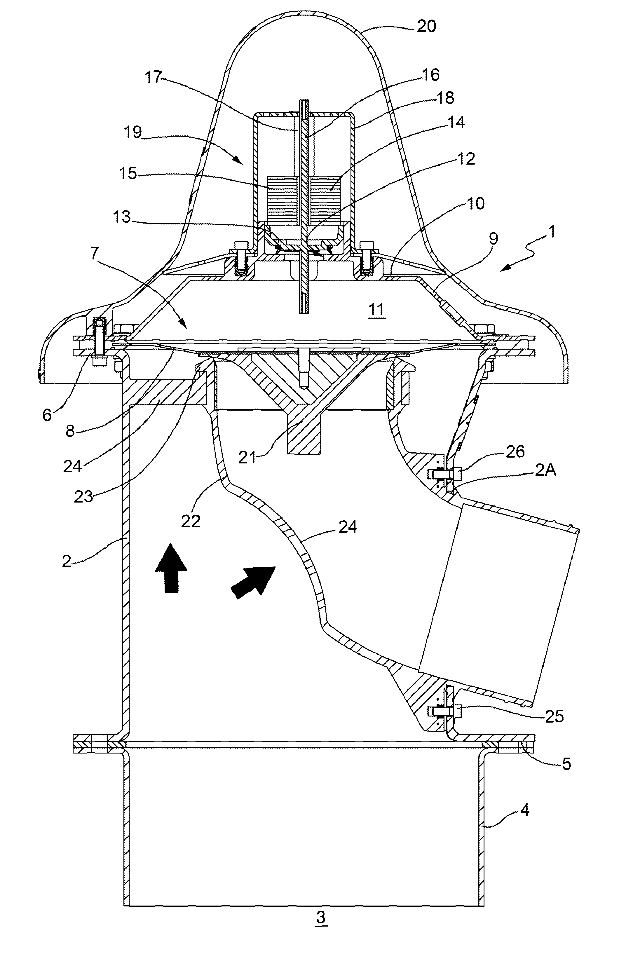
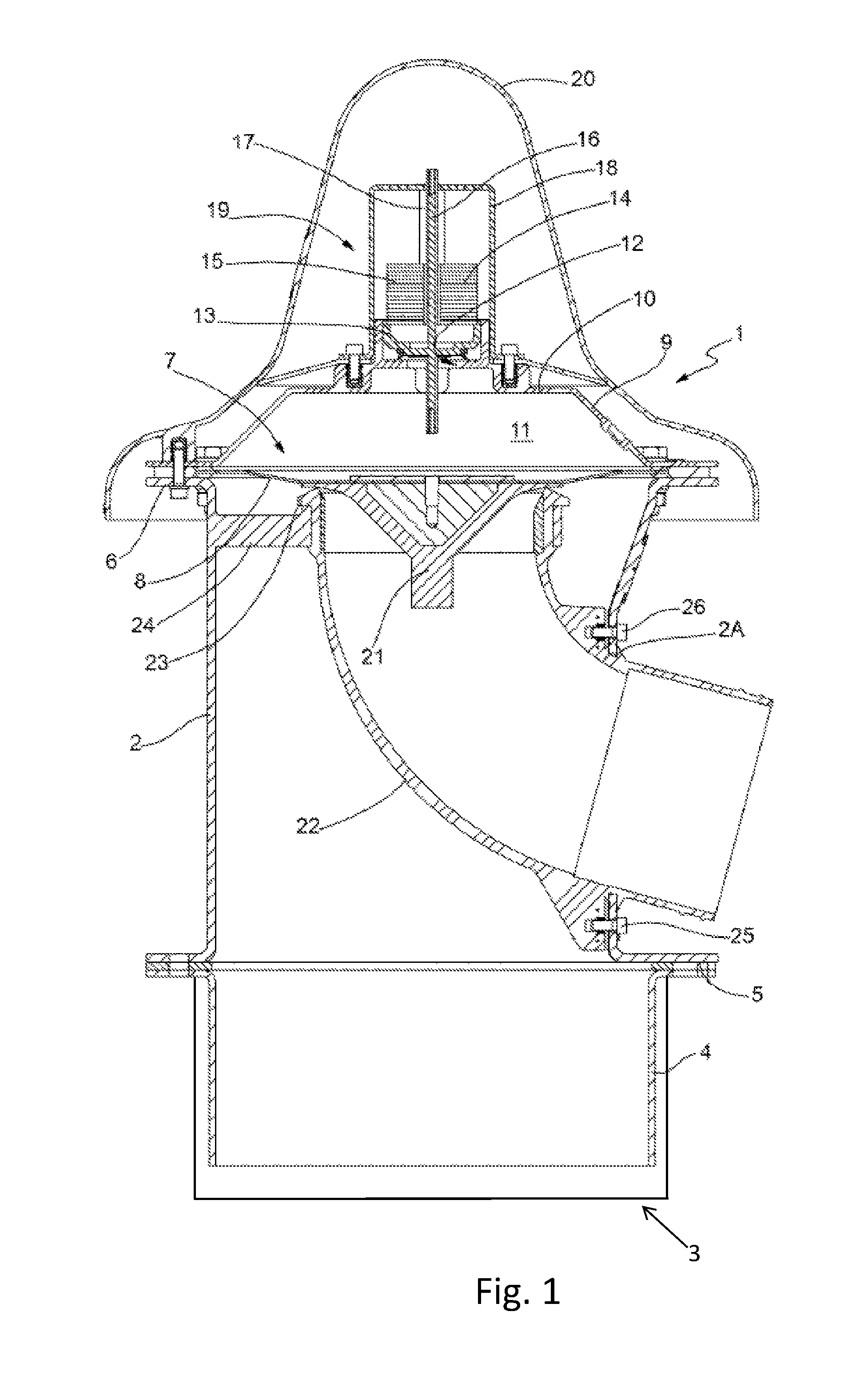
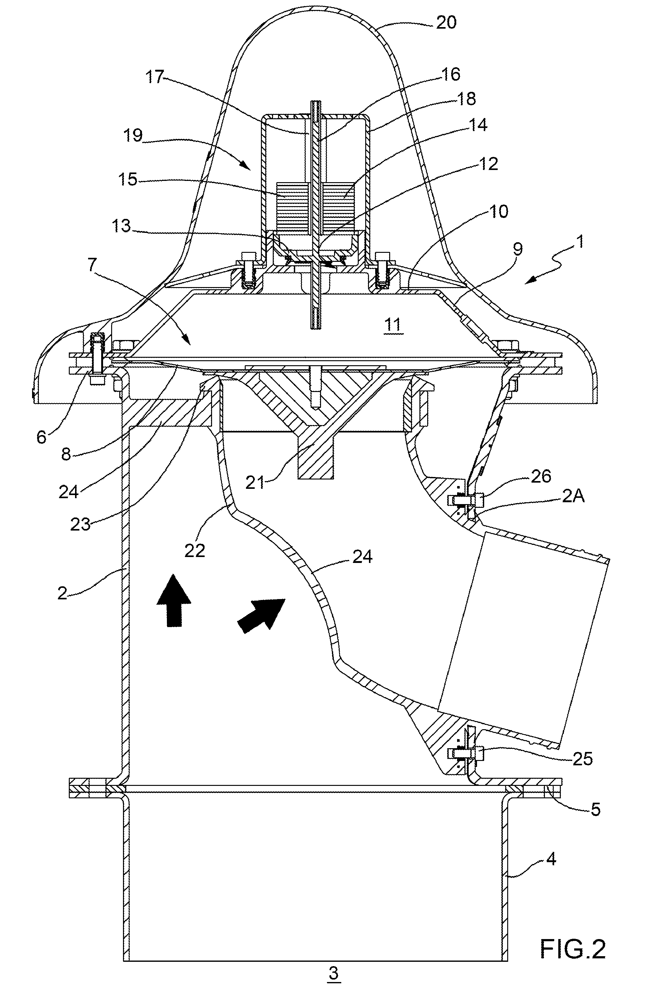
[0019]A pressure relief valve 1 according to the present invention comprises a valve body 2, which pneumatically communicates with the inside of the container 3, for example a silo.

[0020]The valve body 2 of the valve 1 is connected to a sleeve 4, which is integral to the container 3, by means of a flange connection 5.

[0021]The upper end of the valve body 2 is provided with peripheral anchoring means 6 of the flow control organ 7, which preferably comprises, in turn, an elastic membrane 8, which is anchored along its external edge to the anchoring means 5.

[0022]The valve body 2 extends upwards, beyond the membrane 8, in a cap 9, which is provided, in its upper part, with a transverse end wall 10, which delimits, in the upper part, an intermediate chamber 11.

[0023]Therefore, the intermediate chamber 11 is delimited, in turn, by the cap 9 and by the membrane.

[0024]The transverse wall 10 is provided with an opening 12, on which a flow control body 13 rests, on which a calibration mass 1...


PUM


Abstract

A pressure relief valve for containers suited for the pneumatic loading of loose solid products, in particular silos. The valve comprises a valve body having a first end, which pneumatically communicates with the inside of the container, and a second end, which is associated to a flow control organ, which is subject to the action of corresponding closing membrane. The flow control organ periodically establishes a fluid communication between said valve body and a duct that communicates with the outside. The valve is characterized in that at least one portion of the duct that communicates with the outside is suited to be elastically deformed by the pressure difference existing between the inside of said container and the inside of the duct itself.

Description

CROSS REFERENCE TO RELATED APPLICATIONS[0001]The present application is a U.S. National Phase of International Patent Application PCT / IB2012 / 056690, filed Nov. 23, 2012, which claims priority to Italian Patent Application No. BO2011A000668, filed Nov. 23, 2011, each of which is incorporated herein by reference in its entirety.TECHNICAL FIELD[0002]The present invention is relative to a pressure relief valve for containers suited for the pneumatic loading of loose solid products.[0003]In particular, the present invention finds advantageous, but not exclusive, application in silos, to which explicit reference will be made in the description below without because of this loosing in generality.BACKGROUND ART[0004]Pressure relief valves are well known in containers under pressure, such as for example silos, which are provided with a metal discharge duct, which can be connected to a further pipe for conveying powders to a confined and protected area.[0005]Even tough these valves work in an...

Claims


Application Information

Patent Timeline
Patent Type & Authority Patents(United States)
IPC IPC(8): F16K15/14F16K17/02B65G53/12B65G53/54B65G53/60F16K17/164F16K17/12
CPCF16K17/02B65G53/12B65G53/54B65G53/60F16K17/12F16K17/164Y10T137/788
Inventor MARCHESINI, VAINERGOLINELLI, LUCA
Owner WAMGRP
Why Eureka
Try Eureka