Electronic lighting device simulating real fire

a lighting device and electronic technology, applied in the direction of semiconductor devices for light sources, light and heating apparatus, free standing, etc., can solve the problems of ferromagnets not being able to satisfactorily utilize magnetic force, unable to always position ferromagnets, and unable to achieve the effect of satisfying the magnetic force, facilitating production process, and strong magnetic for

Active Publication Date: 2016-12-27
WU SHANGQIANG
View PDF7 Cites 8 Cited by
  • Summary
  • Abstract
  • Description
  • Claims
  • Application Information

AI Technical Summary

Benefits of technology

[0003]In view of the aforesaid disadvantages now present in the prior art, the present invention provides a structurally simple and compact electronic lighting device simulating real fire which helps reduce manufacturing costs. The inventor has discovered that the balanced condition of the pendulum member can be easily disturbed at the supporting point. A slight amount of external force exerted to the supporting point can cause the pendulum member to lose its balance and therefore swing. Therefore, the pendulum member can swing well regardless of whether attractive force or repulsive force is created between the magnetic pole of the magnetic field of the electromagnetic coil and the magnetic pole of the ferromagnet. Hence, it is not necessary to check the pole direction of the ferromagnet, thereby shortening the manufacturing process and thus facilitating production. Furthermore, when a pendulum member according to the existing prior art swings, the ferromagnet cannot be always positioned within a strong magnetic field of the electromagnetic coil and thus cannot satisfactorily utilize the magnetic force. As such, the electromagnetic coil requires stronger current to drive the pendulum member to swing reciprocally. On the contrary, the present invention positions the drive mechanism corresponding to the middle part of the pendulum member, so that when the flame sheet swings, the ferromagnet is always positioned within the strong magnetic field of the electromagnetic coil. Therefore, the magnetic force can be much better utilized and thus a weaker current should be sufficient to drive the flame sheet to swing reciprocally.
[0015]The present invention having the above described structure has the following advantages:
[0017]2. The ferromagnet is surrounded by the electromagnetic coil or proximate to an outer side of the center of the electromagnetic coil, so the ferromagnet receives stronger magnetic force, thereby receiving better driving force from the electromagnetic coil. Since the present invention positions the drive mechanism corresponding to the middle part of the flame sheet, the ferromagnet is always positioned within the strong magnetic field of the electromagnetic coil when the flame sheet swings. Therefore, the magnetic force can be much better utilized and thus a weaker current should be sufficient to drive the flame sheet to swing reciprocally.
[0018]3. The balanced condition of the pendulum member can be easily disturbed at the supporting point. A slight amount of external force exerted to the supporting point can cause the pendulum member to lose its balance and therefore swing. Therefore, the pendulum member can swing well regardless of whether attractive force or repulsive force is created between the magnetic pole of the magnetic field of the electromagnetic coil and the magnetic pole of the ferromagnet. Hence, it is not necessary to check the pole direction of the ferromagnet, thereby facilitating production process.

Problems solved by technology

A slight amount of external force exerted to the supporting point can cause the pendulum member to lose its balance and therefore swing.
Furthermore, when a pendulum member according to the existing prior art swings, the ferromagnet cannot be always positioned within a strong magnetic field of the electromagnetic coil and thus cannot satisfactorily utilize the magnetic force.

Method used


Image

  • Electronic lighting device simulating real fire
  • Electronic lighting device simulating real fire
  • Electronic lighting device simulating real fire

Examples


Embodiment Construction

[0036]The present invention is further described in detail below with reference to embodiments and the accompanying drawings.

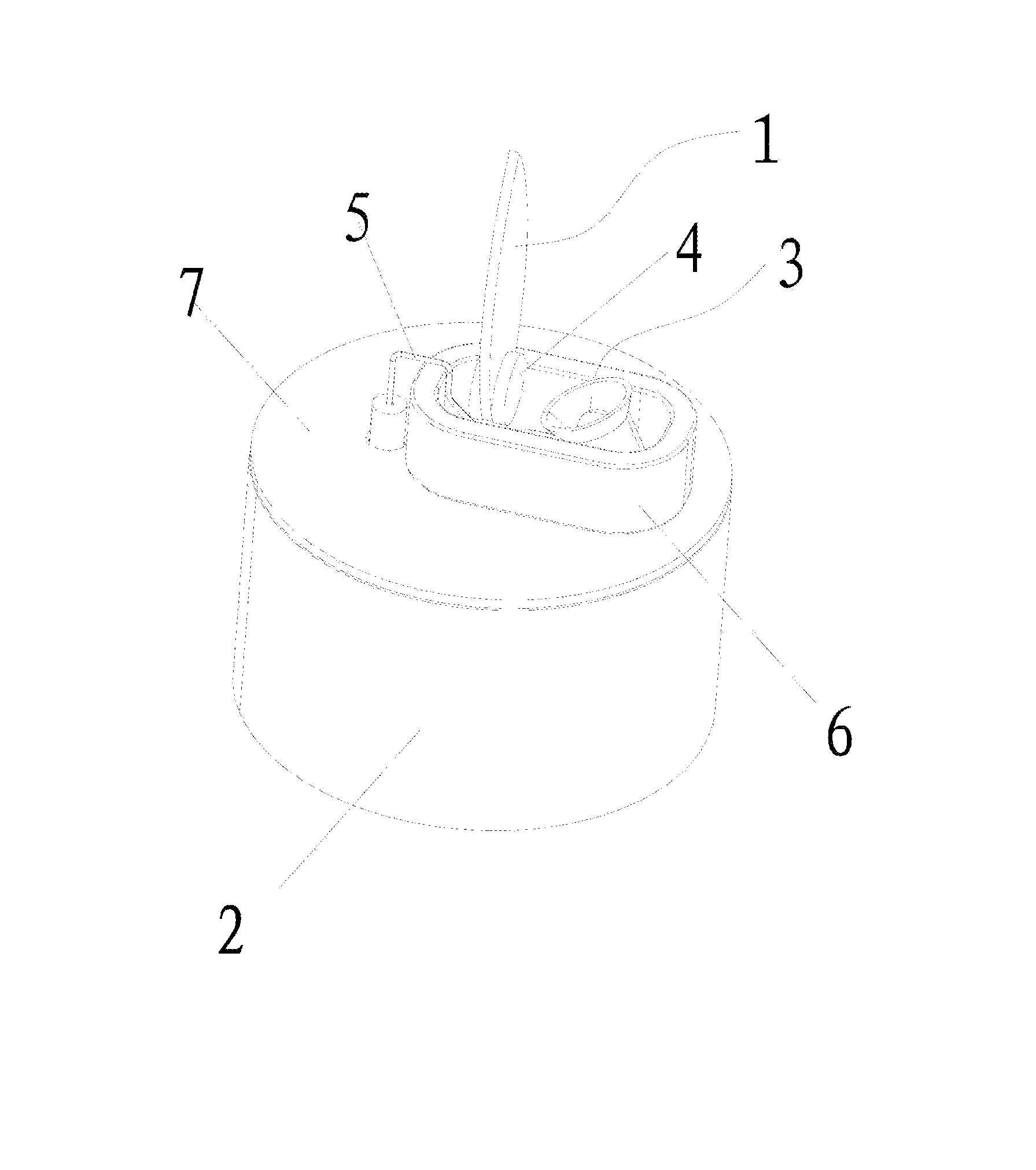
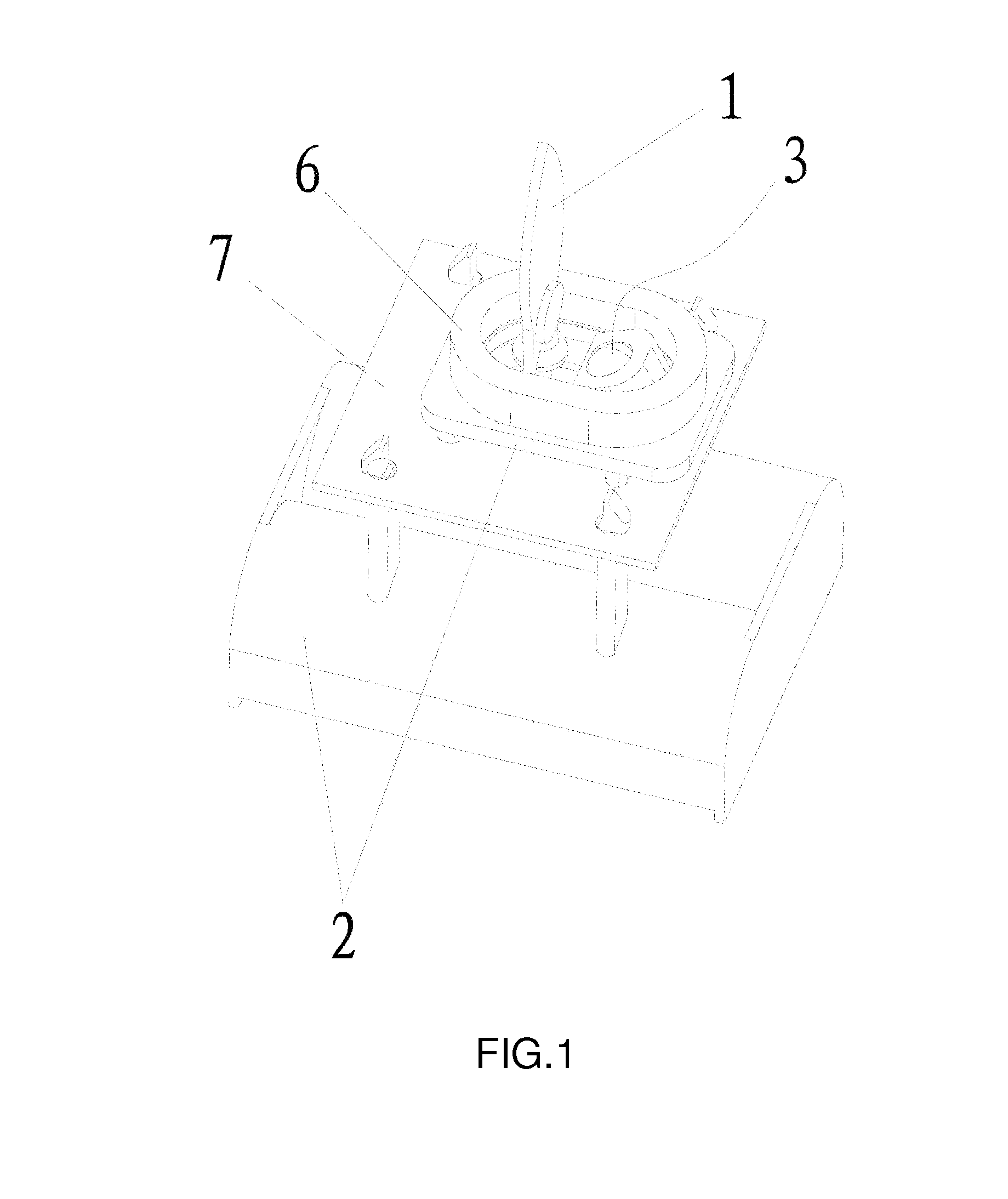
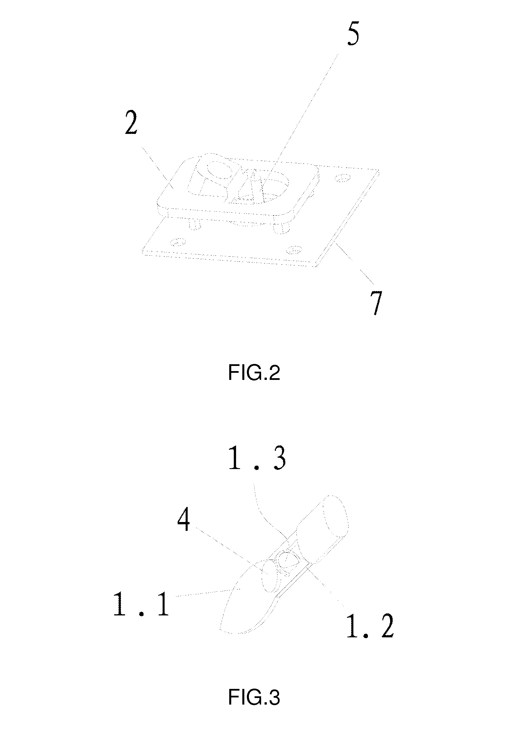
[0037]As shown in FIGS. 1-9, an electronic lighting device simulating real fire according to the present invention is mainly an assembly of the following components: a flame sheet 1, a supporting frame 2, a light emitting element 3 and a drive mechanism. Specifically, the supporting frame 2 serves a supporting function; each of other components has to rely on the supporting frame 2 in order to be installed, assembled or fixed. During use, a power supply is also mounted onto the supporting frame 2. The supporting frame 2 can have different specific shapes and structures based on specific needs. The light emitting element 3 can be any light bulb or LED light. The light emitting element 3 should emit light towards the flame sheet 1. The light emitting element 3 is connected with the power supply via a circuit board 7. If necessary, some other small components can...


PUM


Abstract

An electronic lighting device simulating real fire comprising a flame sheet (1), a supporting frame (2), a light emitting element (3) and a drive mechanism; the flame sheet (1) comprises a flame section (1.1), a balance section (1.2) and a supporting point (1.3); the supporting point (1.3) is positioned between the flame section (1.1) and the balance section (1.2); the drive mechanism is positioned corresponding to a middle part of the flame sheet (1); the drive mechanism exerts driving force to the middle part of the flame sheet (1). The electronic lighting device simulating real fire has a compact design. When the flame sheet swings, the ferromagnet is always positioned within the strong magnetic field of the electromagnetic coil. Therefore, the magnetic force can be much better utilized and thus a weaker current should be sufficient to drive the flame sheet to swing reciprocally.

Description

BACKGROUND OF THE INVENTION[0001]The present invention relates to a kind of electronic lighting device simulating real fire.[0002]In daily life, various kinds of electronic lighting devices which serve simulating functions are widely used by various ornamentation and toys. These electronic lighting devices are much safer than traditional real fire and they can be controllably adjusted on demand. These electronic lighting devices create joyful user's experience. However, existing electronic lighting devices simulating candle flame are heavy, structurally complicated and contain too many internal structural components, thereby increasing processing costs such as manufacturing and installation costs. Chinese granted patent CN101865413B, published on 20 Oct. 2010, discloses an “electronic lighting device for simulating real fire and method for simulating real fire by the electronic lighting device”, according to which “the electronic lighting device for simulating real fire comprises a ...

Claims


Application Information

Patent Timeline
Patent Type & Authority Patents(United States)
IPC IPC(8): F21S10/04F21S6/00F21V14/08F21W121/00F21Y115/10
CPCF21S10/046F21S6/001F21V14/08F21W2121/00F21Y2101/00F21Y2115/10
Inventor WU, SHANGQIANG
Owner WU SHANGQIANG
Why Eureka
Try Eureka