
Radionavigation signal tracking device

a technology of radioonavigation and tracking device, which is applied in the field of radioonavigation, can solve the problems of ambiguous phase measurement, high risk of dropout, and unknown number of integer cycle between the satellite and the receiver, and achieve the effect of increasing the robustness of phase measuremen

Active Publication Date: 2016-12-27
CENT NAT DETUD SPATIALES (CNES) +1
View PDF10 Cites 0 Cited by
  • Summary
  • Abstract
  • Description
  • Claims
  • Application Information

AI Technical Summary

Benefits of technology

[0008]The invention is directed toward increasing the robustness of phase measurements.
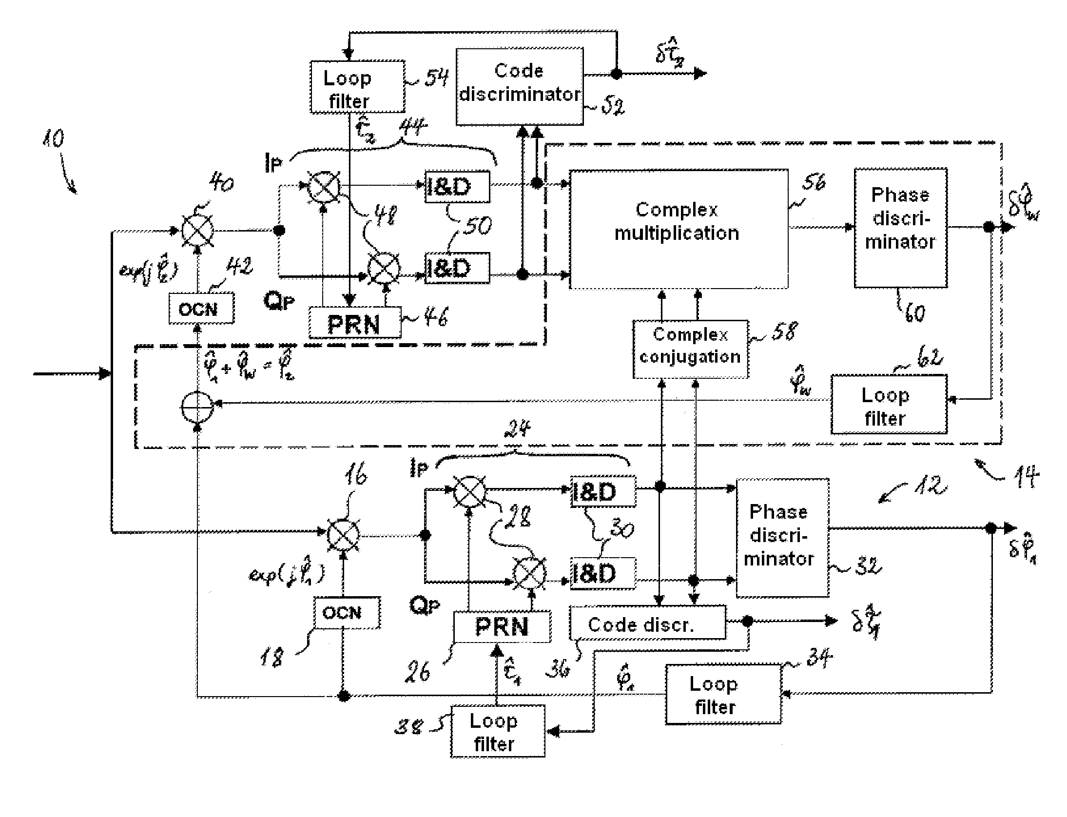
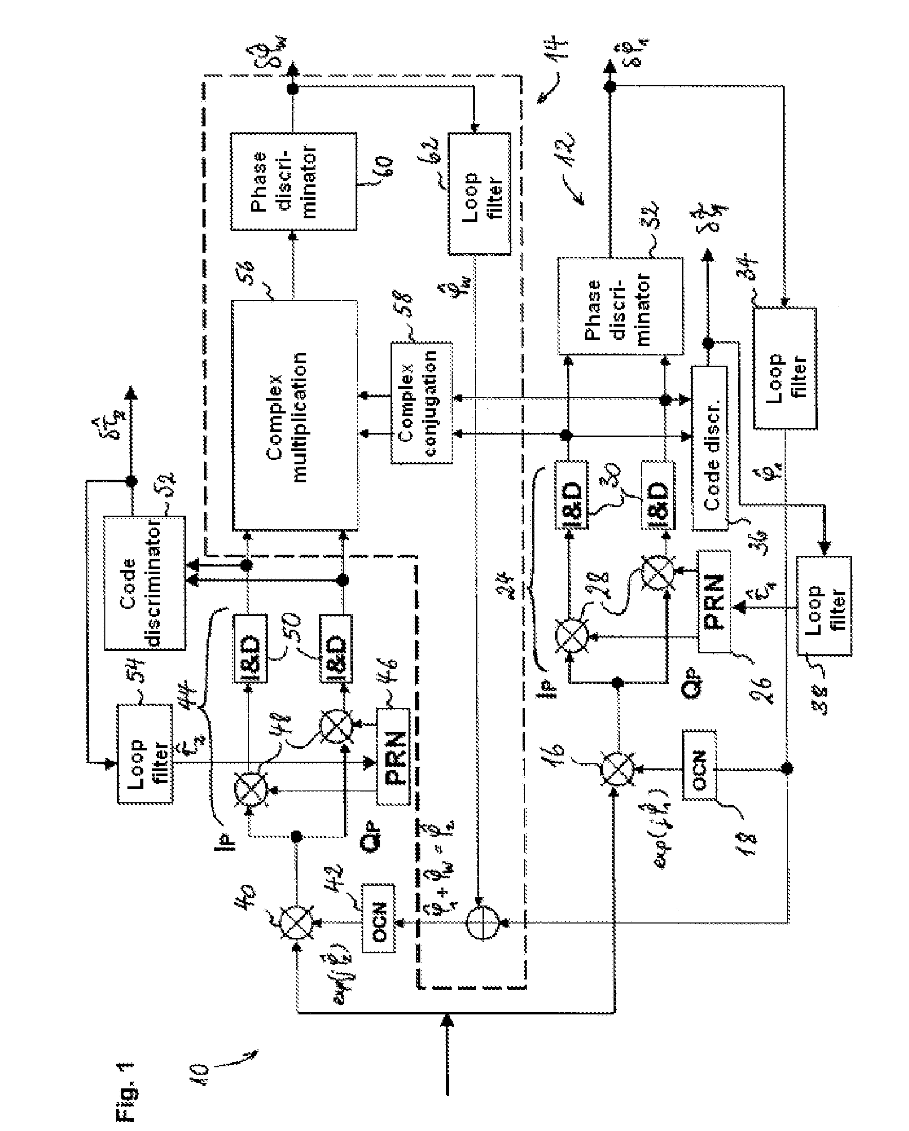
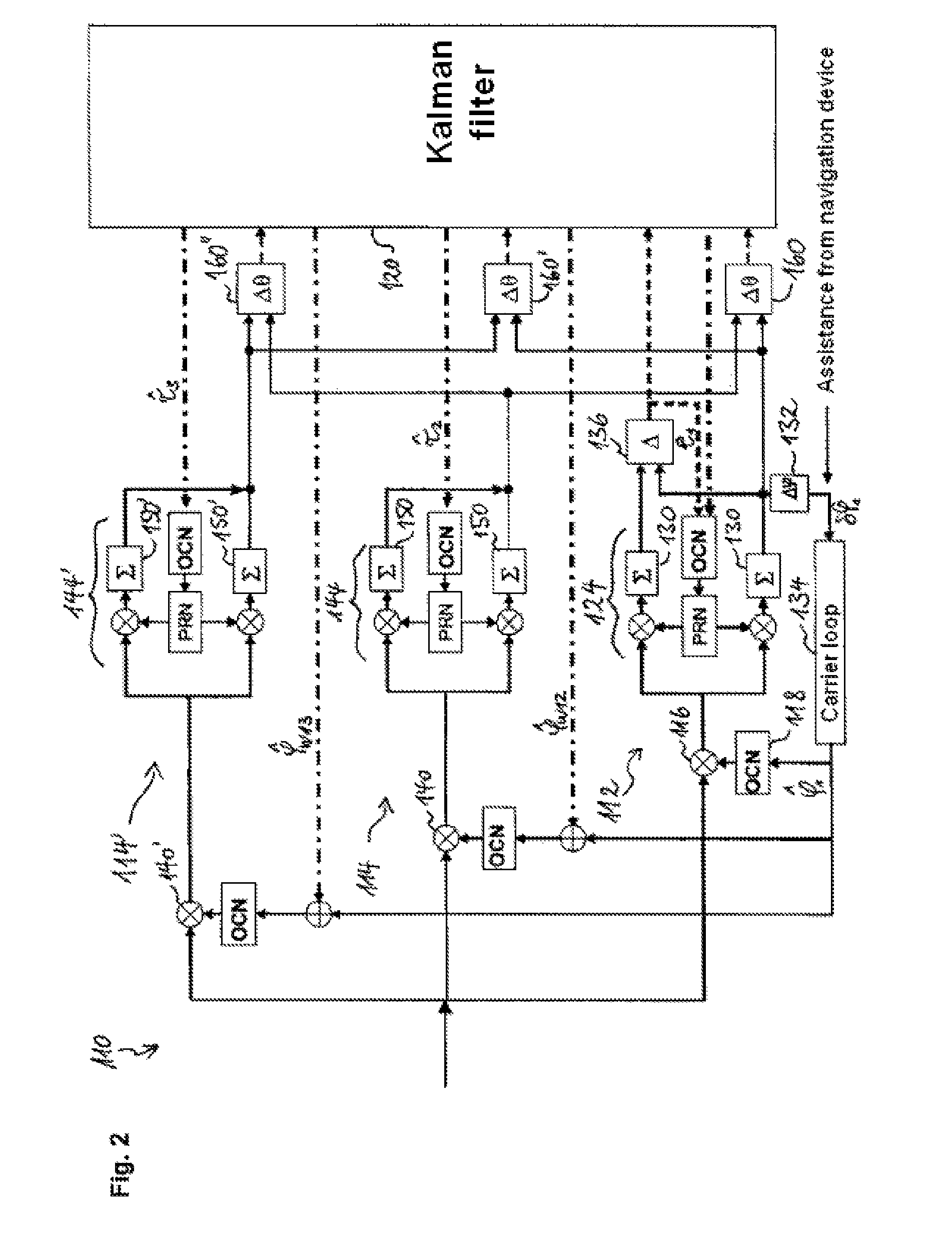
[0010]It will be noted that the device according to the invention may be used for the purposes of a dual-frequency or multifrequency GNSS receiver. Instead of tracking the first and second radionavigation signals individually (i.e. using separate phase tracking loops), the tracking device of the invention uses phase-locked loops which are coupled to one another. The phase of the first radionavigation signal is tracked on the basis of the first error signal while the phase of the second radionavigation signal is tracked by using the first error signal and the second error signal which is dependent on the beat phase between the two carriers. In the present document, the term “beat” denotes the periodic variation in the amplitude of oscillation arising from the composition of two carriers. The beat signal has the frequency |f1−f2| where f1 and f2 respectively represent the first and the second carrier frequency. The beat phase is dependent on the phase of each of the two carriers. It is intuitively clear that knowing the phase of one of the carriers and the beat phase makes it possible to obtain the phase of the other carrier. In the tracking device according to the invention, the phase tracking loop of the second carrier adjusts the phase of the local replica of the second carrier by using this property. One advantage of this approach is that the device according to the invention only directly tracks the phase of the first carrier. The second phase-locked loop tracks the beat, which is at a frequency (|f1−f2|) distinctly lower than the frequency of the second carrier. Since this frequency is lower, the number of phase jumps per unit time is considerably reduced relative to the carriers, which makes measurement of the beat phase highly robust. The method used by the device according to the invention thus permits more robust joint tracking of the phase of two radionavigation signals originating from the same transmitter (satellite or pseudolite).
[0012]Preferably, the first and second radionavigation signals are selected from among Galileo E1, E5 and E6 signals or among GPS L5, L2C and L1 signals or alternatively among GLONASS L3, G2 and G1 signals. The method used by the device according to the invention is particularly advantageous if the carrier phase tracking of one of the signals is significantly more robust than the tracking of the other signal(s). In such a situation, the signal having the most robust carrier phase tracking may be selected as the first radionavigation signal. The carrier phase of the other radionavigation signals need not be tracked directly but may be identified on the basis of the beat phase. According to one advantageous embodiment of the invention, the first radionavigation signal is a Galileo E5 signal and the second radionavigation signal is a Galileo E1 signal or a Galileo E6 signal. Due to the “AltBOC” modulation of the Galileo E5 signal, the carrier phase of this signal can be more robustly tracked than that of the E1 (CBOC modulation) or E6 signal.

Problems solved by technology

However, phase measurements have the major drawback of being ambiguous in that the number of integer cycles between the satellite and the receiver is unknown at the outset.
The risk of dropout is much higher than for code tracking.
Furthermore, managing cycle slip is a difficult task.
In a challenging environment (for example in an urban area), availability of phase measurements is likely to be very low, so making receivers capable of carrying out and processing phase observations very much less worthwhile.

Method used


Image

  • Radionavigation signal tracking device
  • Radionavigation signal tracking device
  • Radionavigation signal tracking device

Examples


Embodiment Construction

[0027]A radionavigation signal receiver can carry out code measurements (which are unambiguous) and phase measurements (ambiguous in terms of an integer number of cycles) on the radionavigation signals which it receives from the various satellites which are in visibility (i.e. above the horizon). A multifrequency receiver may carry out these measurements on at least two distinct carrier frequencies f1 and f2. Assuming a dual-frequency receiver, for each satellite in visibility and at each time step (tk), there may therefore be two code measurements, notated P1j(tk) and P2j(tk), and two phase measurements, notated φ1j(tk) and φ2j(tk), on the frequencies f1 and f2, where upper index (j) indicates the transmitter (satellite or pseudolite) from which the signal arriving at the receiver originates. Since the satellites orbit the Earth, only some of them are visible at a given moment from the location of the receiver. To simplify notation, time dependence and the satellite index will not ...


PUM


Abstract

A radionavigation signal tracking device comprises a first and a second tracking stage for radionavigation signals. The first tracking stage comprises a first carrier phase-locked loop. The latter produces a first error signal arising from a phase difference between the first carrier and its replica. The phase of the replica of the first carrier is adjusted with the first error signal. The second tracking stage comprises a second carrier phase-locked loop. The latter produces a second error signal arising from a difference between the first phase difference and a phase difference between the second carrier and the replica thereof. The phase of the replica of the second carrier is adjusted with the first and second error signals.

Description

FIELD OF THE INVENTION[0001]The present invention relates to the field of radionavigation, more specifically to a device for tracking a radionavigation signal (or radioelectric navigation signal). The field of application of the invention is in particular the reception of radionavigation signals transmitted by satellite positioning system transmitters (known for short as GNSS or “Global Navigation Satellite System”), for example GPS (“Global Positioning System”), Galileo, Glonass, QZSS, Compass, IRNSS, etc.BACKGROUND OF THE INVENTION[0002]Generally, the radionavigation signals transmitted by the satellites (or pseudolites) of a positioning system take the form of a carrier modulated by a spreading waveform containing a pseudo-random binary code. Since modulating the carrier causes spreading of the spectrum around the frequency of the carrier, radionavigation signals are frequently referred to as “spread-spectrum”. The pseudo-random codes constitute an identifier of the signal and th...

Claims


Application Information

Patent Timeline
Patent Type & Authority Patents(United States)
IPC IPC(8): G01S19/29G01S19/44G01S1/02
CPCG01S1/02G01S19/29G01S19/44
Inventor VIGNEAU, WILLYJARDAK, NABILPAIMBLANC, PHILIPPEPUENGNIM, ANCHALEERIES, LIONEL
Owner CENT NAT DETUD SPATIALES (CNES)
Learn More