
Developer accommodating unit, process cartridge, and electrophotographic image forming apparatus

a technology of development equipment and process cartridges, applied in the direction of electrographic process equipment, optics, instruments, etc., can solve the problem of difficult effect of sealing, and achieve the effect of improving the sealing characteristic of the sealing member

Active Publication Date: 2016-12-27
CANON KK
View PDF55 Cites 50 Cited by
  • Summary
  • Abstract
  • Description
  • Claims
  • Application Information

AI Technical Summary

Benefits of technology

[0012]An object of present invention is in the developer unit using the flexible container for accommodating the developer, to improve an unsealing characteristic of the sealing member for sealing the opening of the flexible container.
[0014]According to the present invention, in the developer accommodating unit using the flexible container for accommodating the developer, it is possible to improve the unsealing characteristic of the sealing member for sealing the opening of the flexible container.

Problems solved by technology

However, in the above-described conventional example, there was the following problem
However, in the case where the developer is accommodated in the deformable developer accommodating member, the opening of the deformable developer accommodating member is pulled together with the toner seal during unsealing, so that it becomes difficult to effect the unsealing.

Method used


Image

  • Developer accommodating unit, process cartridge, and electrophotographic image forming apparatus
  • Developer accommodating unit, process cartridge, and electrophotographic image forming apparatus
  • Developer accommodating unit, process cartridge, and electrophotographic image forming apparatus

Examples


first embodiment

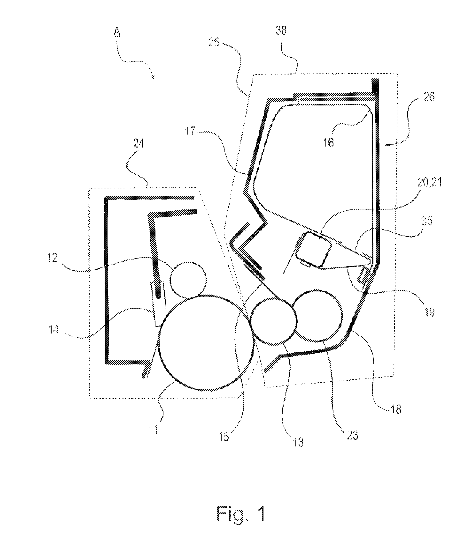
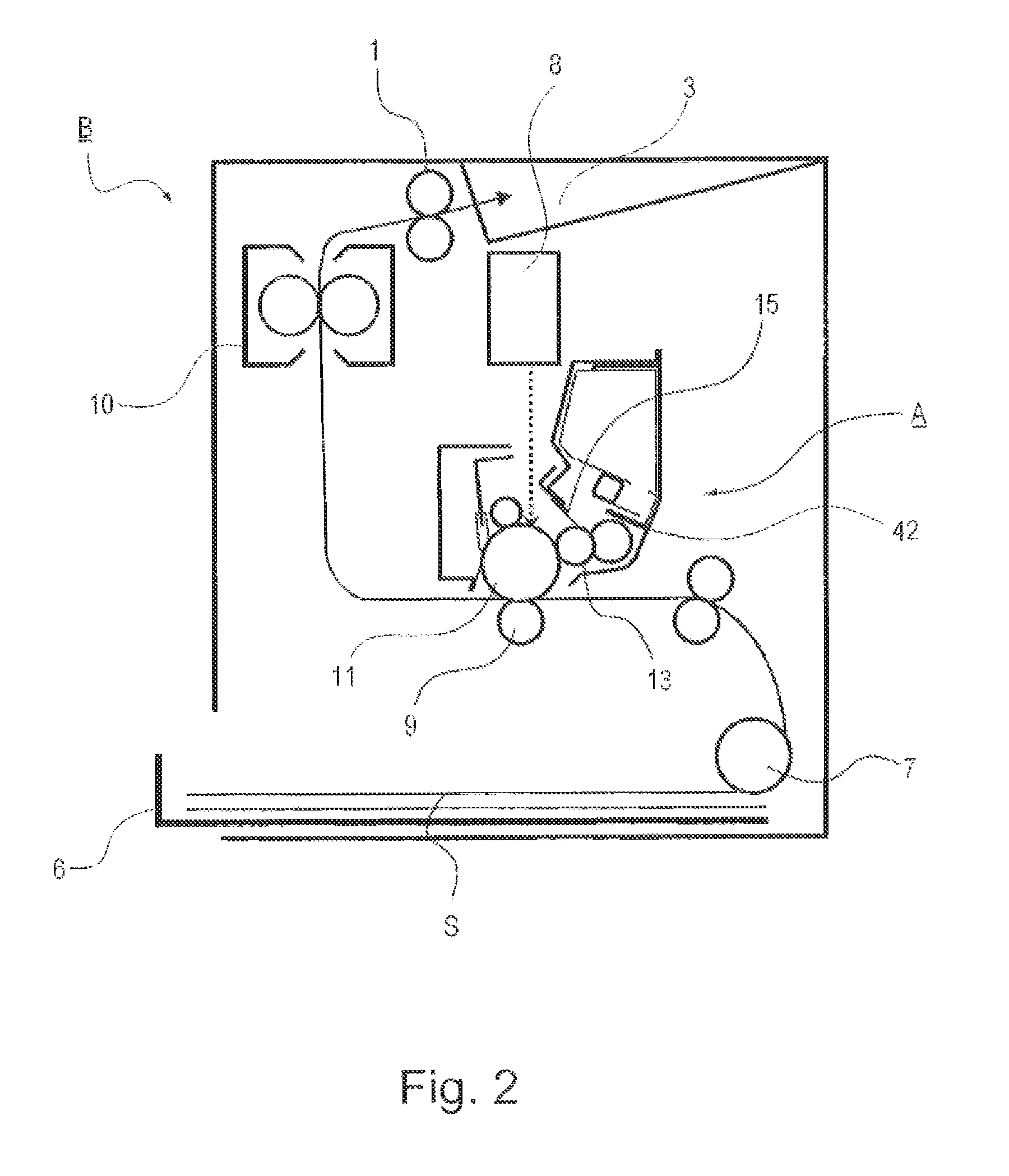
[0054]FIG. 1 illustrates a principal sectional view of a process cartridge including the developer accommodating unit to which the present invention is applicable, and FIG. 2 illustrates a principal sectional view of an image forming apparatus to which the present invention is applicable.

[0055]The process cartridge includes an image bearing member (electrophotographic photosensitive member) and process means actable on the image bearing member. Here, as the process means, there are, e.g., a charging means for electrically charging a surface of the image bearing member, a developing device for forming an image on the image bearing member, and a cleaning means for removing a developer (containing toner, carrier, etc.) remaining on the image bearing member surface.

[0056]The process cartridge A in this embodiment includes, as shown in FIG. 1, includes a photosensitive (member) drum 11 as the image bearing member and includes, at a periphery of the photosensitive drum 11, a charging roll...

second embodiment

[0205]Elements having constitution and functions (actions) which are identical or correspond to those in First Embodiment are represented by the same symbols and will be omitted from detailed description.

[0206]As described above, in First Embodiment, the multi-layer structure portion 16g where the sheet 36u or the sheet 16s is superposed by being folded back is constituted, but the multi-layer structure portion is not limited thereto.

[0207]In this embodiment, as shown in (a) of FIG. 35, the outside of the bonding together portion 16i of each of the sheet 16u and the sheet 16s is extended, so that a portion where the sheet 16u and the sheet 16s constitute the two layers is the multi-layer structure portion 16g. Further, a constitution in which at this multi-layer structure portion 169, the first fixing portion 16d as the fixed portion is disposed is employed.

[0208]As in First Embodiment, in the case where the multi layer structure portion 16g where the sheet is superposed by being fo...

third embodiment

[0212]As shown in FIG. 18, FIG. 19 and FIG. 34, in Third Embodiment, in place of the developer bags 16 in First and Second Embodiments, a developer accommodating member 34 is used.

(Vacuum Molding)

[0213]In the following, details of the developer accommodating member 34 will be described. The developer accommodating member 34 is formed by shaping a sheet-like material by vacuum molding, air-pressure molding or press molding, and is used. The developer accommodating container 30 including the unsealing member includes, similarly as in First Embodiment, the developer accommodating member 34, the sealing member 19, the unsealing member 20, the first frame 17 and the second frame 18. Incidentally, the unsealing member 20 is a member having the function of the urging member 21 and the developer stirring function similarly as in First Embodiment 1.

(Structure of Developer Bag)

[0214]As shown in FIG. 18 and (a) of FIG. 34, the developer accommodating member 34 is constituted by a molded portio...


PUM


Abstract

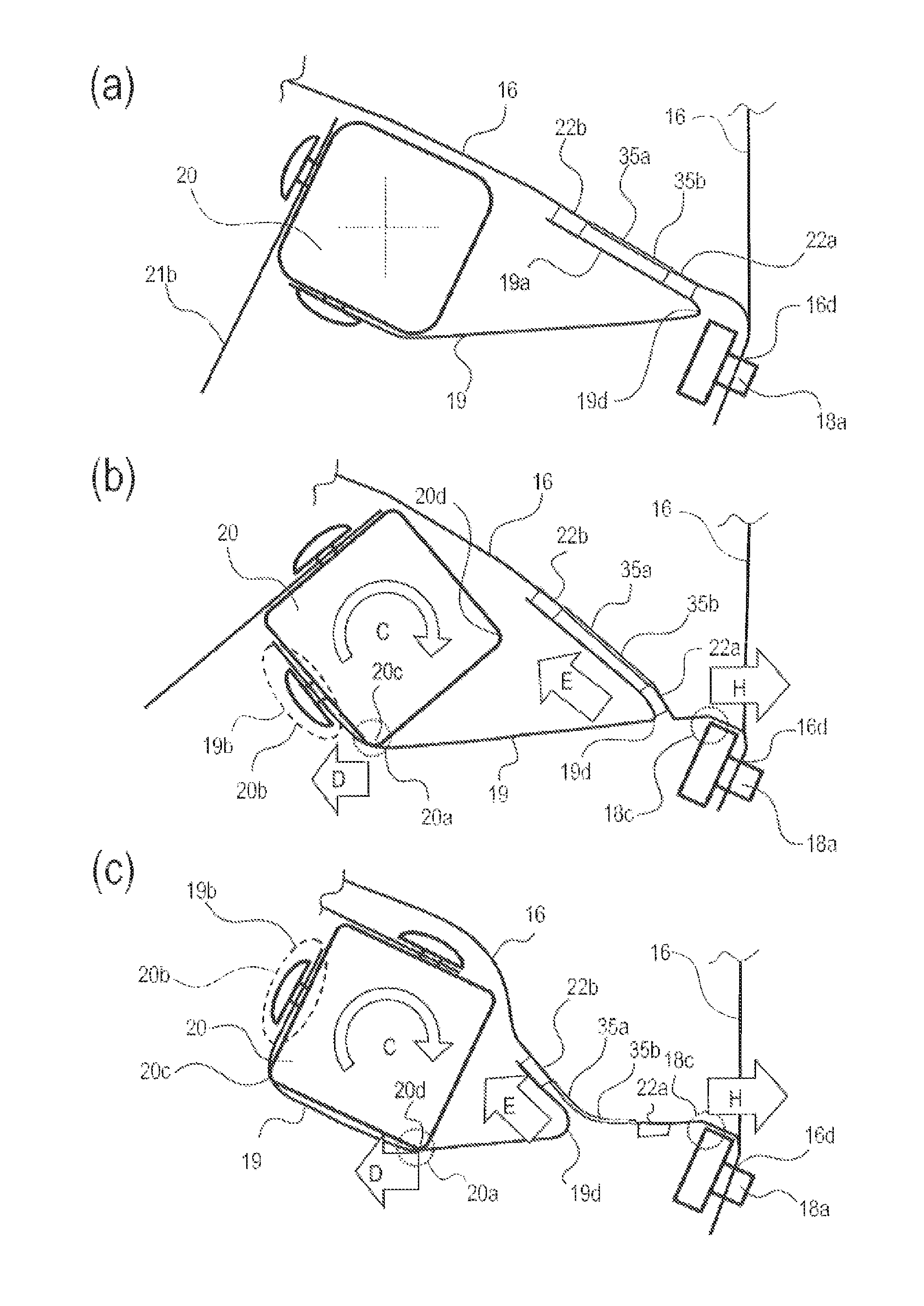
A developer accommodating unit for accommodating a developer for image formation. A flexible container includes a developer accommodating portion for accommodating the developer and an opening for permitting discharge of the developer. The flexible container also includes a superposed multi layer sheet structure portion for forming the developer accommodating portion. A sealing member seals the opening and an unsealing member moves the sealing member to unseal the opening. A frame that accommodates the flexible container, the sealing member, and the unsealing member includes a fixing portion for fixing the flexible container. A fixed portion fixed to the fixing portion is provided at the superposed multi layer sheet structure portion of the flexible container, and an interlayer bonding portion between the superposed layers is provided between the fixed portion of the multi layer sheet structure portion and the developer accommodating portion.

Description

[0001]This application is a continuation application of International Application No. PCT / JP2012 / 068528, filed on Jul. 13, 2012, and published as PCT Publication No. 2013 / 008953 on Jan. 17, 2013.TECHNICAL FIELD[0002]The present invention relates to a developer accommodating unit for accommodating a developer for image formation, a detachably mountable cartridge including the developer accommodating unit, and an electrophotographic image forming apparatus including this cartridge.[0003]Here, the electrophotographic image forming apparatus forms an image on a recording material (medium) by using, e.g., an electrophotographic image forming process and may include, e.g., an electrophotographic copying machine, an electrophotographic printer (such as an LED printer or a laser beam printer), an electrophotographic facsimile machine, and the like.[0004]Further, the cartridge refers to a cartridge including at least a developing means and the developing device which are integrally constitut...

Claims


Application Information

Patent Timeline
Patent Type & Authority Patents(United States)
IPC IPC(8): G03G15/08
CPCG03G15/0881G03G15/08G03G15/0874G03G15/0882
Inventor UESUGI, TETSUOYASUI, KOJIROMATSUSHITA, MASAAKIYOSHIDA, MASATOMIMATSUZAKI, HIROOMIFUJISAKI, TATSUOMATSUMURA, JUNICHIMATSUMOTO, KAZUKI
Owner CANON KK
Learn More