Unlock instant, AI-driven research and patent intelligence for your innovation.

Terminal connection structure

a connection structure and terminal technology, applied in the direction of connection contact material, electrical apparatus, effected by permanent deformation, etc., can solve the problems of terminal mounting portions, affecting the onboard space of electrical circuitry, and affecting the efficiency of bolt tightening terminals. to achieve the effect of high durability and facilitate provision

Active Publication Date: 2016-12-27
SUMITOMO WIRING SYST LTD
View PDF8 Cites 2 Cited by
  • Summary
  • Abstract
  • Description
  • Claims
  • Application Information

AI Technical Summary

Benefits of technology

The structure allows easy and secure alignment and retention of the bolt tightening terminal, preventing misalignment and detachment, while maintaining efficient assembly and ensuring reliable electrical connections.

Problems solved by technology

In recent years, due to the increasing number of electrical components mounted on vehicles and demands for downsizing vehicles, the onboard space for electrical circuitry is increasingly limited.
Additionally, this structure has the inherent problem that the bolt tightening terminal is easily displaced from the proper mounting position in which the bolt insertion hole of the bolt tightening terminal and the threaded hole of the nut are aligned with each other.
This may adversely affect the efficiency with which the bolt tightening terminal is fastened to the terminal mounting portion.
However, this would require a large force to mount the bolt tightening terminal in the terminal mounting portion, again possibly affecting the work efficiency.

Method used


Image

  • Terminal connection structure
  • Terminal connection structure
  • Terminal connection structure

Examples


Embodiment Construction

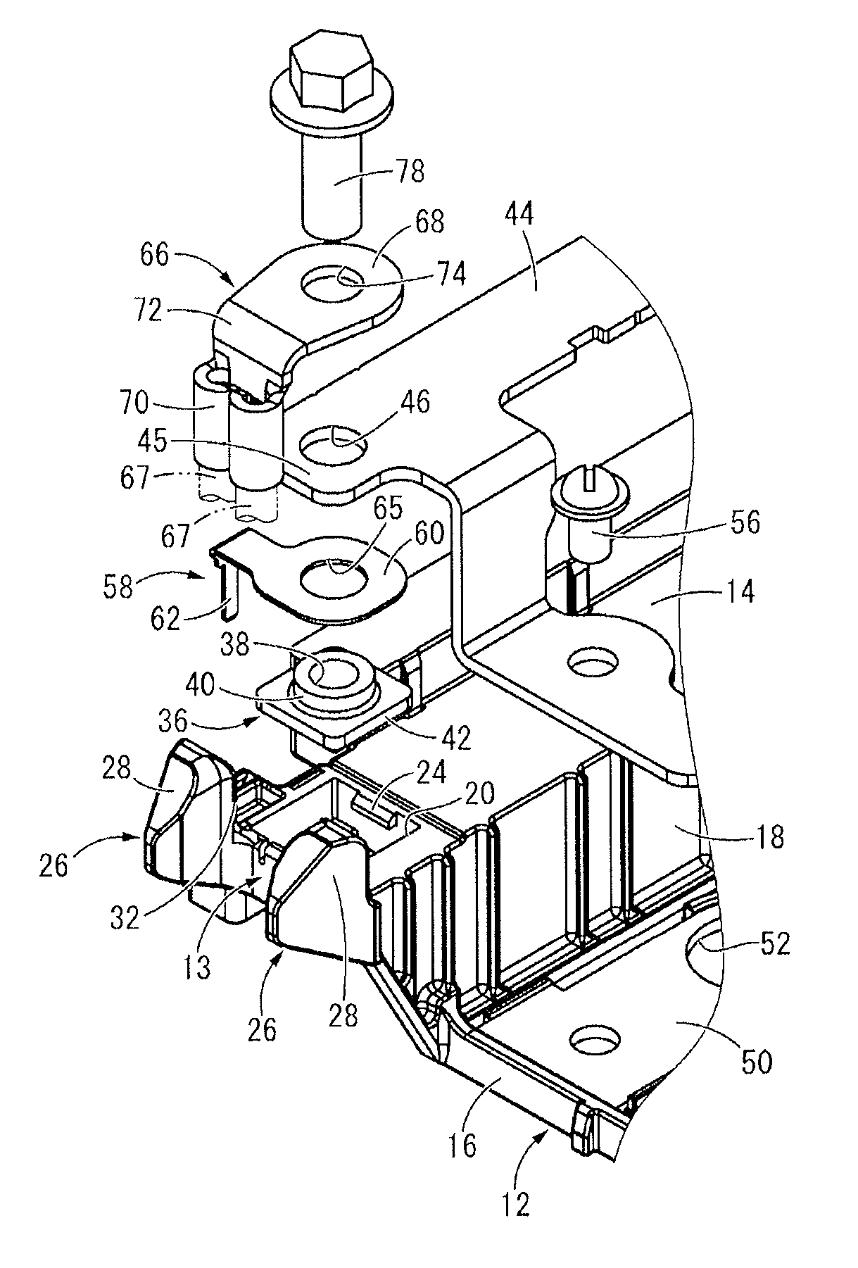
[0028]Embodiments of the present application will be described hereinafter with specific reference to the attached drawings.

[0029]FIGS. 1-3 show a part of an electric circuit, such as a fusible link 11, provided with a terminal connection structure 10, representing a first embodiment of the present application. The fusible link 11 is to be directly attached to a battery post of an automotive battery and has a structure in which conduction members, such as bus bars 44 and 50 (which will be described in detail below), and other components are mounted on a main case body12 can be, in some embodiments made of a synthetic resin. Although omitted from the drawings, the fusible link 11 includes a fuse adapted to be blown by an over-current, thus being capable of preventing overheating of the electrical circuitry connected downstream of the fusible link 11 (e.g., wire harnesses). In the following description, unless otherwise specified, the term “upward / downward direction” as used herein re...


PUM


Abstract

A terminal connection structure is proposed in which a bolt tightening terminal is set on a terminal mounting portion and is fastened with a connecting bolt that is tightened to a nut of the terminal mounting portion. The terminal mounting portion is provided with a displacement limiting portion. If the bolt tightening terminal, set on a terminal mounting portion, is disposed in a proper mounting position in which a bolt insertion hole and a threaded hole are aligned on the same center axis, the bolt tightening terminal is adapted not to interfere with the displacement limiting portion. If the bolt tightening terminal is displaced from the proper mounting position, the bolt tightening terminal is adapted to interfere with the displacement limiting portion to limit the displacement from the proper mounting position.

Description

CROSS-REFERENCE TO RELATED APPLICATIONS[0001]This application claims priority to Japanese Patent Appl. No. 2014-139053 filed on Jul. 4, 2014, the disclosure of which is incorporated herein by reference in its entirety.TECHNICAL FIELD[0002]Embodiments of the present application relate to a terminal connection structure for fastening a bolt fastening terminal provided at an end of an electrical wire to a terminal mounting portion provided on an electric circuit with a bolt.BACKGROUND[0003]Conventionally, electrical circuits, such as electrical connection boxes and fusible links, for use in automotive electrical equipment have been provided with a terminal mounting portion on which conduction members, such as bus bars, that constitute part of the electrical circuit are mounted. Such a conventional electrical circuit employs a terminal connection structure in which the electric circuit is brought into conduction with an electrical wire by fastening to the terminal mounting portion a bol...

Claims


Application Information

Patent Timeline
Patent Type & Authority Patents(United States)
IPC IPC(8): H01R4/34H01R4/64H01R4/18H01R11/12
CPCH01R4/34H01R4/18H01R4/184H01R11/12
Inventor OKUHIRA, YUSUKE
Owner SUMITOMO WIRING SYST LTD