Methods and apparatus for particle aggregation using acoustic standing waves

a technology of acoustic standing waves and particle aggregation, which is applied in the direction of biomass after-treatment, filtration separation, and separation processes, can solve the problems of non-uniform velocity reduction in the vertical flow path, and achieve the effects of improving particle separation, enhancing particle concentration, and improving particle separation

Active Publication Date: 2017-01-03
FLODESIGN SONICS
View PDF7 Cites 29 Cited by
  • Summary
  • Abstract
  • Description
  • Claims
  • Application Information

AI Technical Summary

Benefits of technology

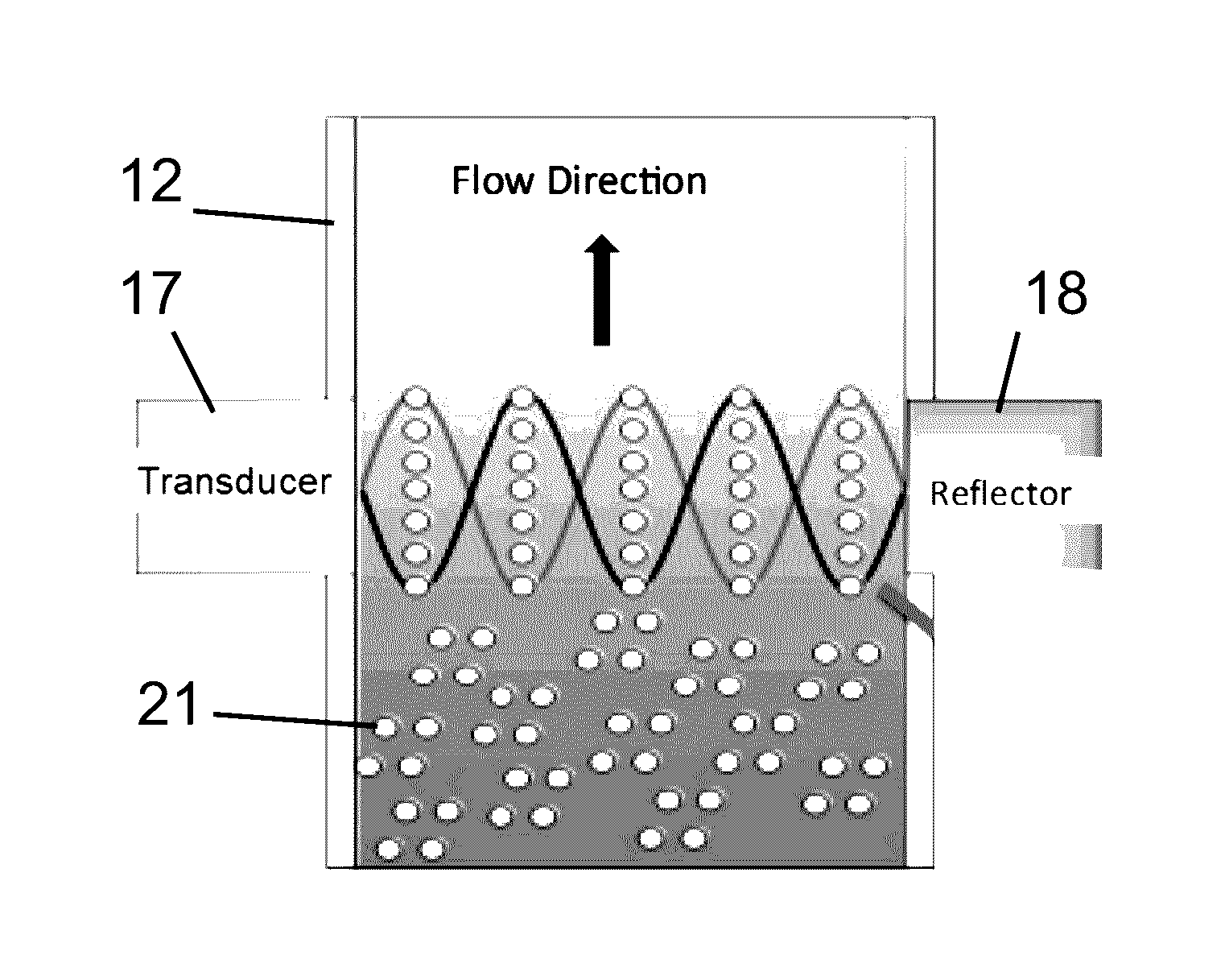
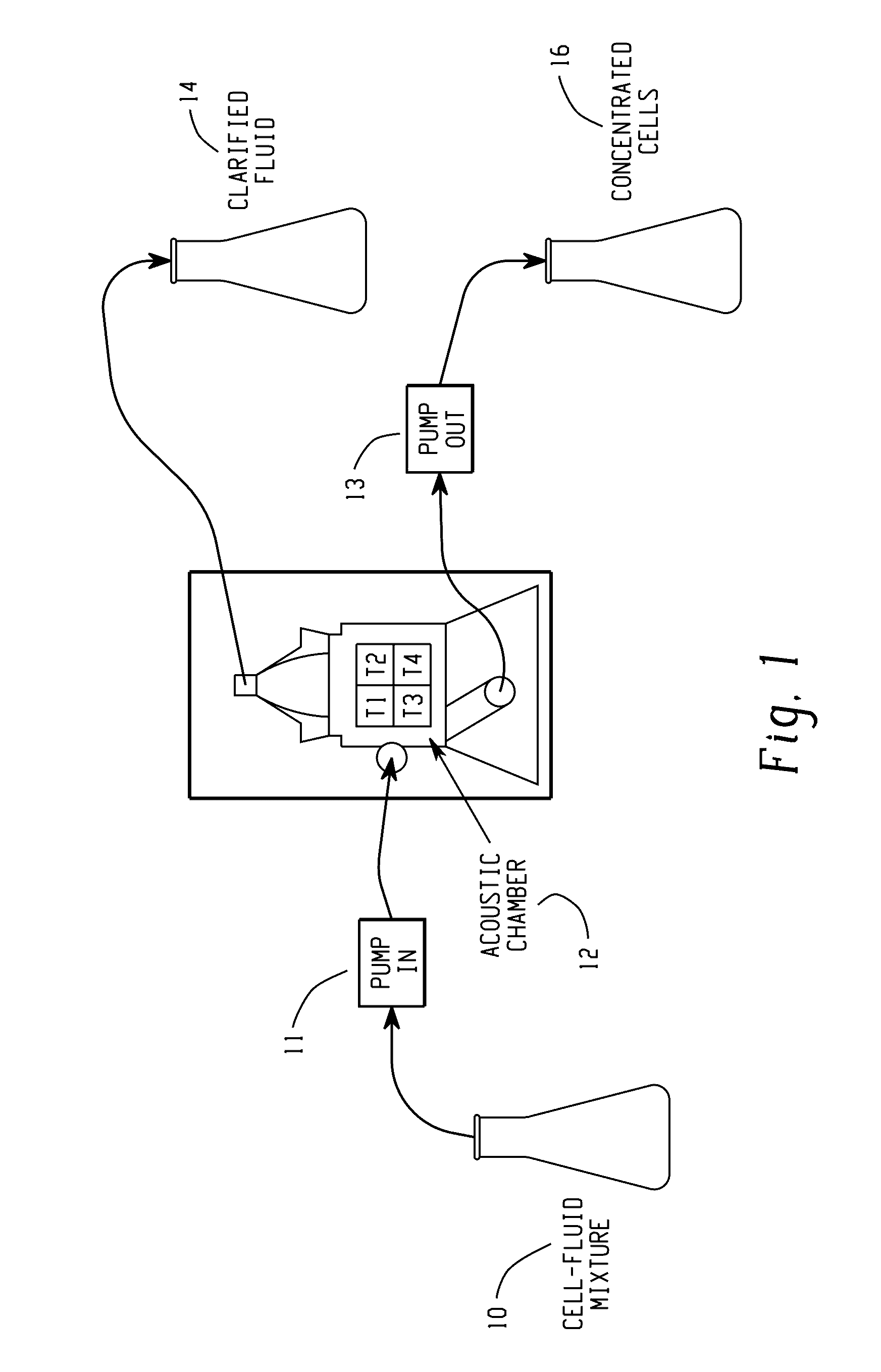
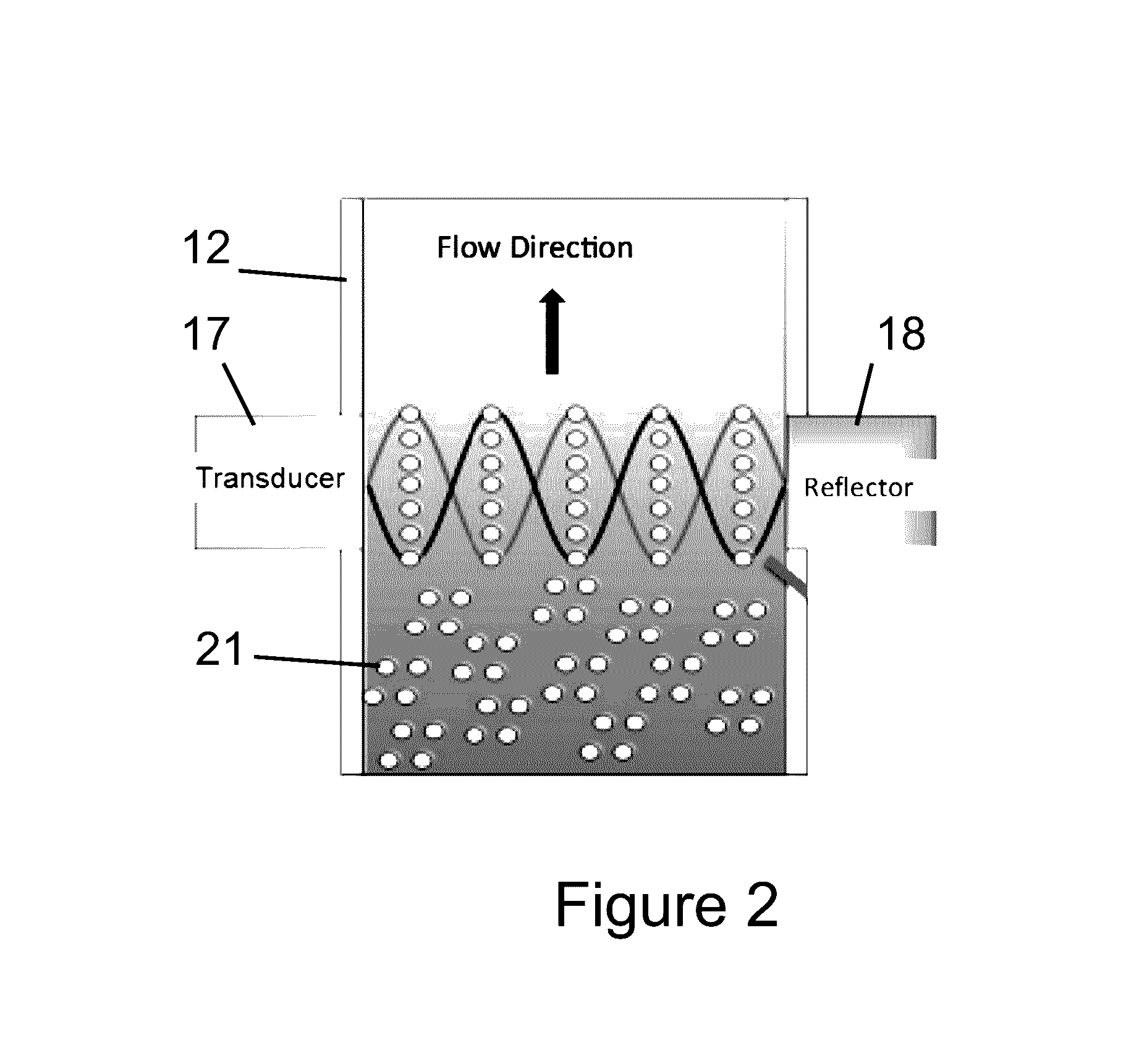
[0010]The present disclosure relates, in various embodiments, to acoustophoretic systems with improved fluid dynamics that can be used to improve the separation of particles from a particle / fluid mixture. More particularly, the systems and methods disclosed herein use reduced frequencies to enhance particle concentration in optimal shapes to improve their separation by gravity and subsequent collection. The systems include an acoustic chamber containing an ultrasonic transducer and reflector that set up a multi-dimensional acoustic standing wave.
[0011]The systems described herein can use a substantially vertical flow path of the mixture through the acoustic chamber in order to improve separation of particles / secondary fluid from a primary fluid using fluid dynamics. The vertical flow path reduces velocity non-uniformities in the acoustic chamber resulting from gravity forces. In additional systems, a dump diffuser is used to make the incoming flow more uniform, so that the efficiency of the acoustophoretic system is maximized. However, the present system is not limited to vertical flow.

Problems solved by technology

The vertical flow path reduces velocity non-uniformities in the acoustic chamber resulting from gravity forces.

Method used


Image

  • Methods and apparatus for particle aggregation using acoustic standing waves
  • Methods and apparatus for particle aggregation using acoustic standing waves
  • Methods and apparatus for particle aggregation using acoustic standing waves

Examples


Embodiment Construction

[0060]The present disclosure may be understood more readily by reference to the following detailed description of desired embodiments and the examples included therein. In the following specification and the claims which follow, reference will be made to a number of terms which shall be defined to have the following meanings.

[0061]Although specific terms are used in the following description for the sake of clarity, these terms are intended to refer only to the particular structure of the embodiments selected for illustration in the drawings, and are not intended to define or limit the scope of the disclosure. In the drawings and the following description below, it is to be understood that like numeric designations refer to components of like function.

[0062]The singular forms “a,”“an,” and “the” include plural referents unless the context clearly dictates otherwise.

[0063]The term “comprising” is used herein as requiring the presence of the named component and allowing the presence o...


PUM

PropertyMeasurementUnit
frequencyaaaaaaaaaa
angleaaaaaaaaaa
frequencyaaaaaaaaaa

Abstract

Devices for separating materials from a host fluid are disclosed. The devices include an acoustic chamber having an inlet and an outlet. An ultrasonic transducer and reflector create a multi-dimensional acoustic standing wave in the acoustic chamber that traps the materials and permits a continuous separation of the materials from the host fluid. The materials and the host fluid can thus be separately collected. Multiple sets of trapping lines are generated by the acoustic standing wave, and the transducer is oriented to minimize cross-sectional area for straight vertical channels between the trapping lines.

Description

CROSS-REFERENCE TO RELATED APPLICATIONS[0001]This application claims priority to U.S. Provisional Patent Application Ser. No. 62 / 162,831, filed on May 18, 2015; and to U.S. Provisional Patent Application Ser. No. 62 / 137,795, filed on Mar. 24, 2015, the disclosures of which are hereby fully incorporated by reference in their entireties.BACKGROUND[0002]When particles are entrained or dispersed in a flowing fluid, aggregation of the particles to form larger clumps is typically due to some attraction or adhesion between the particles or the addition of a flocculating agent that aids in attracting and aggregating the particles. Attractive forces between the particles may be ionic or physical entanglement. Some flocculating agents, such as chitosan, may also be directly attractive to the particles and thus form clumps of particles in the fluid medium.[0003]Typically, after the clumps of particles are formed in the fluid medium, a physical filtration process is utilized to separate the agg...

Claims


Application Information

Patent Timeline
Patent Type & Authority Patents(United States)
IPC IPC(8): B01D41/00B01D21/28C02F1/36C12M1/00
CPCB01D21/283C02F1/36C12M47/02
Inventor PRESZ, JR., WALTER M.CHITALE, KEDARLIPKENS, BART
Owner FLODESIGN SONICS
Why Eureka
Try Eureka