
Air heat exchanger

a heat exchanger and air technology, applied in the field of air heat exchangers, can solve the problems of deteriorating heat exchange efficiency of the cooling medium and the air, and achieve the effects of reducing heat exchange efficiency, increasing thermal resistance of flat tubes, and preventing an increase in ventilation resistan

Active Publication Date: 2017-01-03
HITACHI JOHNSON CONTROLS AIR CONDITIONING INC
View PDF15 Cites 8 Cited by
  • Summary
  • Abstract
  • Description
  • Claims
  • Application Information

AI Technical Summary

Benefits of technology

[0012]According to the invention, an air heat exchanger capable of preventing an increase in ventilation resistance and a decrease in heat exchange efficiency due to condensation water generated on surfaces of heat transfer fins, without increasing thermal resistance of flat tubes and the heat transfer fins, and preventing scattering of water droplets downwind from the heat transfer fins can be provided.

Problems solved by technology

In addition, if the condensation advances and a large amount of condensation water stays between the heat transfer fins, the condensation water may occlude between the heat transfer fins.
If between the heat transfer fins are occluded, ventilation resistance of the air heat exchanger increases, which results in deteriorating heat exchange efficiency of the cooling medium and the air.

Method used


Image

  • Air heat exchanger
  • Air heat exchanger
  • Air heat exchanger

Examples


first embodiment

[0033]An air heat exchanger according to a first embodiment of the present invention will be described in detail. This embodiment is an example of the case in which a width of water guiding grooves decreases gradually toward communicating portions with water draining grooves to decrease an area of a cross section of the water guiding grooves.

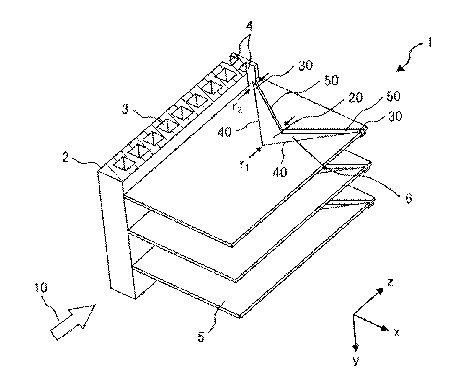
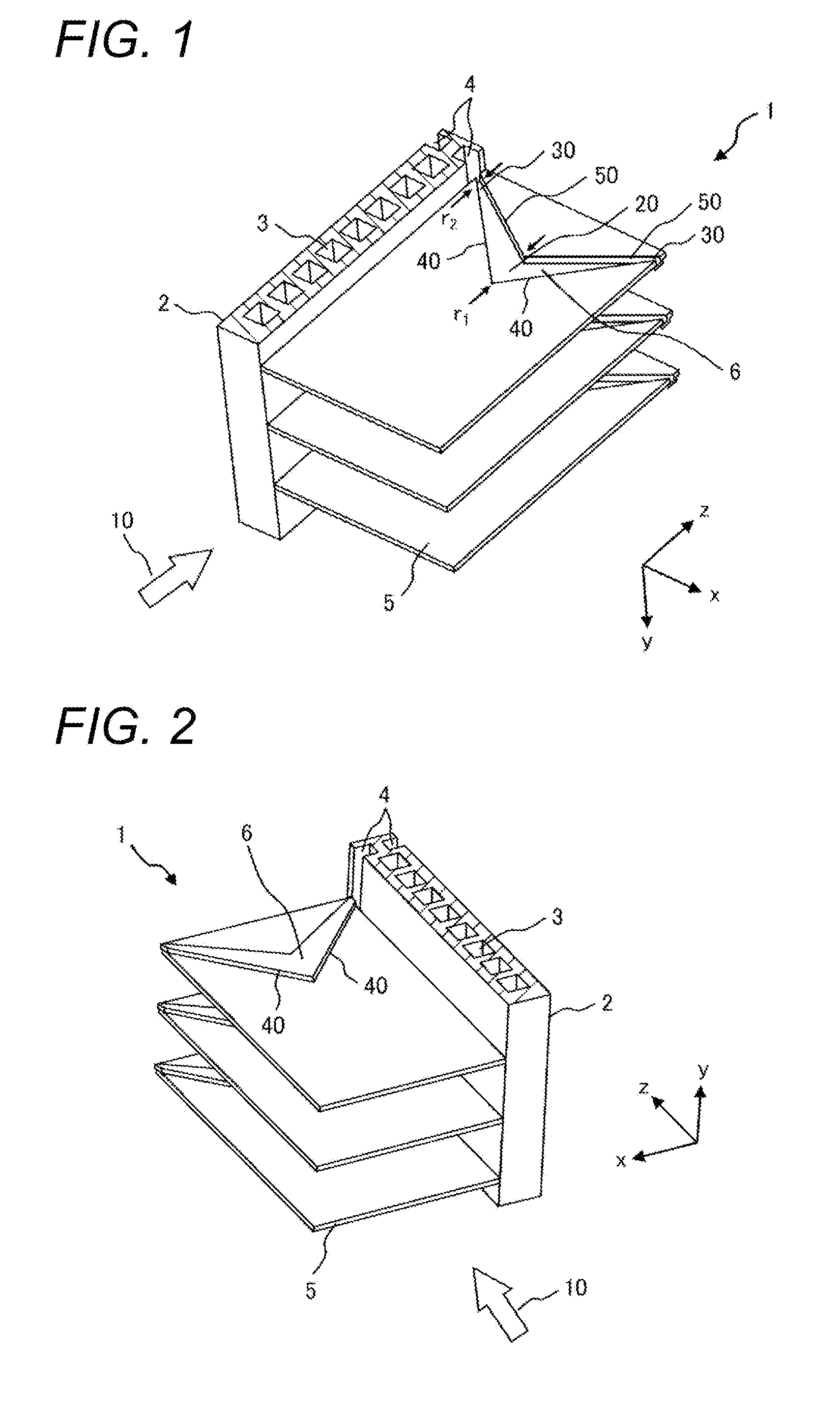
[0034]FIG. 1 is a partial perspective view of an air heat exchanger 1 according to the first embodiment and illustrates a flat tube 2 and a heat transfer fin 5. On the air heat exchanger 1, air is blown by a fan (not illustrated in the drawings). In the drawing, an X axis shows a width direction of the air heat exchanger 1. An X-axis direction is also a width direction of the heat transfer fin 5. In addition, a positive direction of a Y axis shows a gravity direction and a positive direction of a Z axis shows an air blowing direction 10 of the air by the fan. Words “upwind” and “downwind” used in the following description show directions for the...

second embodiment

[0064]An air heat exchanger according to a second embodiment of the present invention will be described. This embodiment is an example of the case in which a heat transfer fin 5 includes a plurality of water guiding grooves 6 in the air heat exchanger 1 according to the first embodiment. In the air heat exchanger 1 according to the present invention, the number of water guiding grooves 6 formed in the heat transfer fin 5 is not limited to one and may be plural. Hereinafter, the air heat exchanger 1 including the heat transfer fin 5 having the plurality of water guiding grooves 6 will be described using the air heat exchanger 1 of the case in which the number of water guiding grooves 6 is two as an example. The following description can be applied to the case in which the number of water guiding grooves 6 is three or more.

[0065]FIGS. 7 and 8 are partial perspective views of the air heat exchanger 1 including the heat transfer fin 5 having the two water guiding grooves 6 and illustrat...

third embodiment

[0071]An air heat exchanger according to a third embodiment of the present invention will be described. This embodiment is an example of the case in which a width of a water guiding groove decreases stepwise toward a communicating portion with a water draining groove to decrease an area of a cross section of the water guiding groove.

[0072]FIG. 9 is a partial perspective view of an air heat exchanger 1 according to the third embodiment and illustrates a flat tube 2 and a heat transfer fin 5. In FIG. 9, the same reference numerals as those of FIG. 1 denote the same elements as those of FIG. 1 and explanation of these elements is omitted.

[0073]A water guiding groove 7 communicating with a water draining groove 4 is formed in the heat transfer fin 5. A width of the water guiding groove 7 decreases stepwise (in three steps in the example of FIG. 9) from an upwind end portion 20 to a communicating portion 30 with the water draining groove 4. A position of the upwind end portion 20 of the ...


PUM


Abstract

Provided is an air heat exchanger capable of preventing an increase in ventilation resistance and a decrease in heat exchange efficiency due to condensation water generated on surfaces of heat transfer fins, without increasing thermal resistance of flat tubes and the heat transfer fins, and preventing scattering of water droplets downwind from the heat transfer fins. In the air heat exchanger including a plurality of flat tubes 2 and heat transfer fins 5 provided between the flat tubes 2 and on which air is blown, the flat tubes 2 include water draining grooves 4 on side surfaces on which the heat transfer fins 5 are provided and the heat transfer fins 5 include water guiding grooves 6 communicating with the water draining grooves 4. At least a groove wall 40 on the upwind side of an air blowing direction 10 among groove walls forming the water guiding grooves 6 is provided from a position of the upwind side from the water draining grooves 4 to the water draining grooves 4. The water guiding grooves 6 extend toward the water draining grooves 4 along the groove wall 40 on the upwind side and an area of a cross section perpendicular to an extension direction decreases toward the water draining grooves 4.

Description

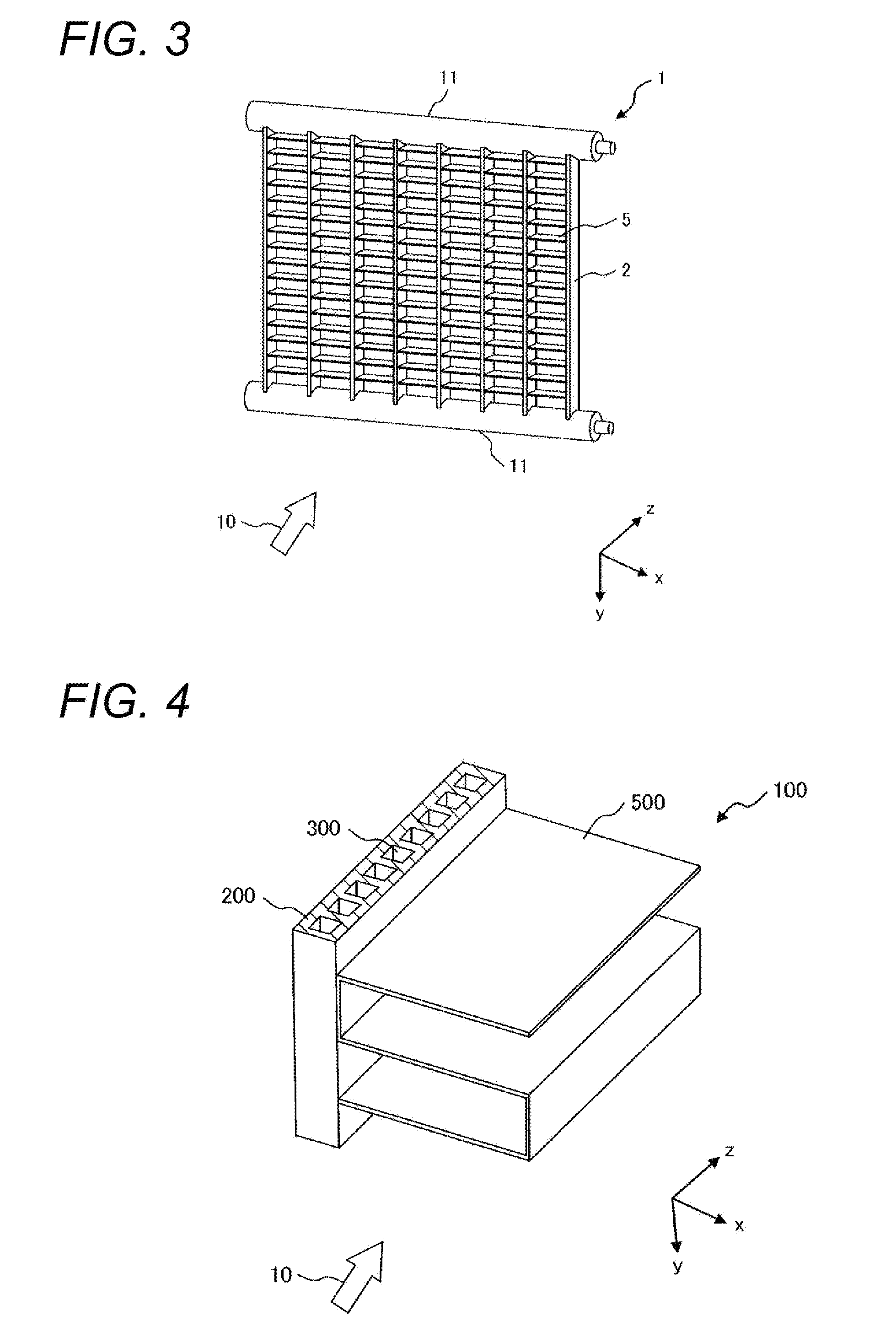
TECHNICAL FIELD[0001]The present invention relates to an air heat exchanger that includes flat tubes and heat transfer fins.BACKGROUND ART[0002]An air heat exchanger includes two tubular headers through which a cooling medium flows, a plurality of flat tubes arranged to couple the two headers, and a plurality of heat transfer fins provided between the plurality of flat tubes. Each of the flat tubes is orthogonal to the header and each of the heat transfer fins is orthogonal to the flat tube. A plurality of minute flow channels communicating from the headers are formed in the flat tubes. The cooling medium flows from the header to the flat tube through the flow channel. Each of the header, the flat tube, and the heat transfer fin is formed of a metal material having high thermal conductivity, for example, aluminum. These members are bonded to each other by a brazing material or an adhesive material. Air is blown on the air heat exchanger having such a structure using a fan and the ai...

Claims


Application Information

Patent Timeline
Patent Type & Authority Patents(United States)
IPC IPC(8): F25D21/14F28F1/32F28F17/00F28D1/053F28F1/12F28D21/00
CPCF25D21/14F28D1/05383F28F1/128F28F1/325F28F17/005F28D2021/0071F25B39/02
Inventor SATO, WATARUSASAKI, SHIGEYUKI
Owner HITACHI JOHNSON CONTROLS AIR CONDITIONING INC
Learn More