
Method and algorithm for functional critical paths selection and critical path sensors and controller insertion

a technology of functional critical paths and algorithm, applied in the field of computer-aided design, can solve problems such as logistical difficulties, slower chips or faster chips, and not always reproducible or planned

Inactive Publication Date: 2017-01-03
QUALCOMM INC
View PDF6 Cites 30 Cited by
  • Summary
  • Abstract
  • Description
  • Claims
  • Application Information

AI Technical Summary

Benefits of technology

This patent is about a computer-aided design (CAD) software application that selects critical paths in a circuit to measure and adjust power-supply voltage in real-time. The software uses a non-provisional application for provisional patenting, and a provisional patent describes a method for selecting critical paths to add sensors to. The software automatically selects which paths to add sensors to based on process variations, and adjusts the power-supply voltage to account for these variations. The software also selects paths that are the slowest but without causing timing hazards that could disrupt sensor accuracy. Overall, the software helps improve the accuracy and efficiency of CAD design for semiconductor devices.

Problems solved by technology

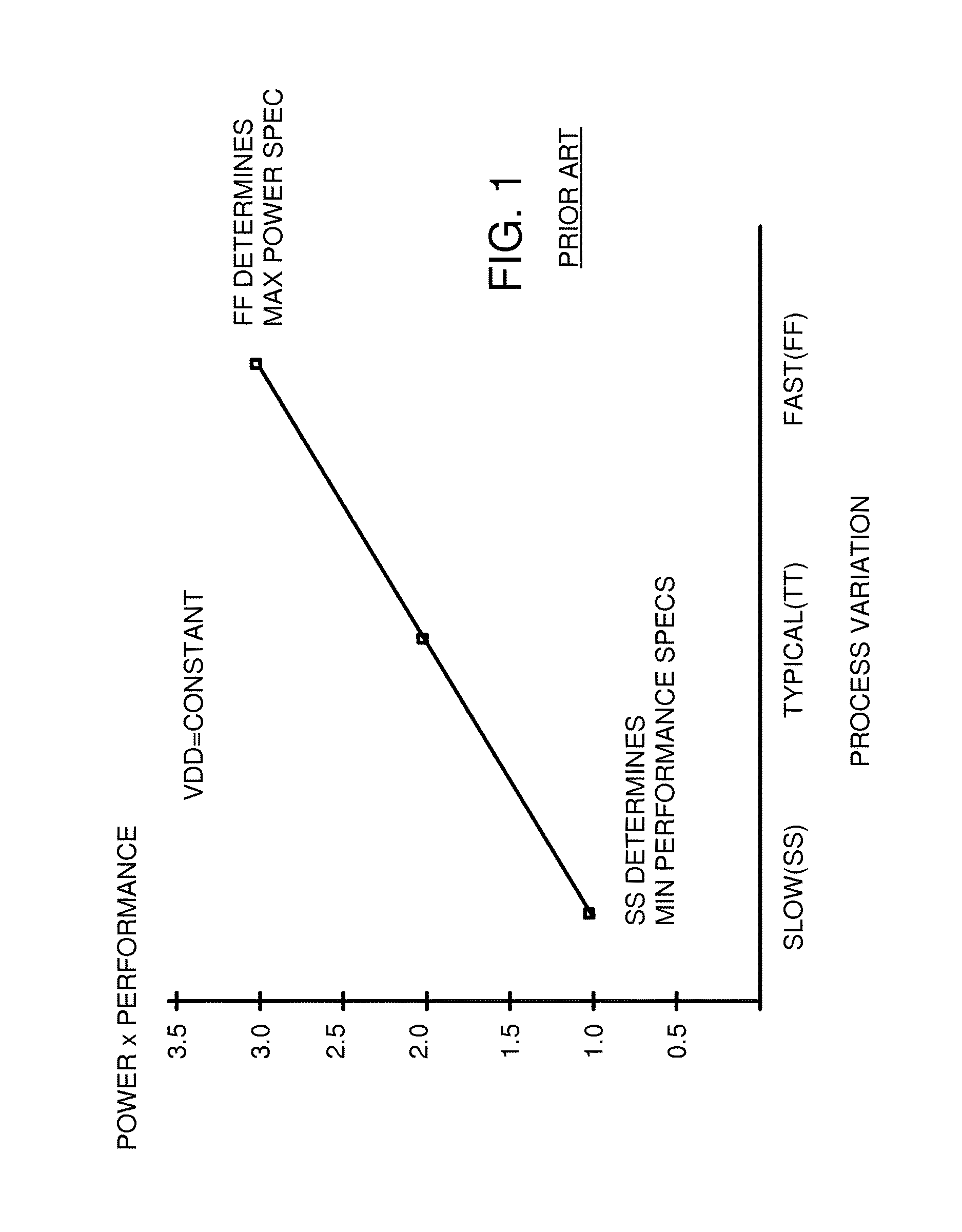
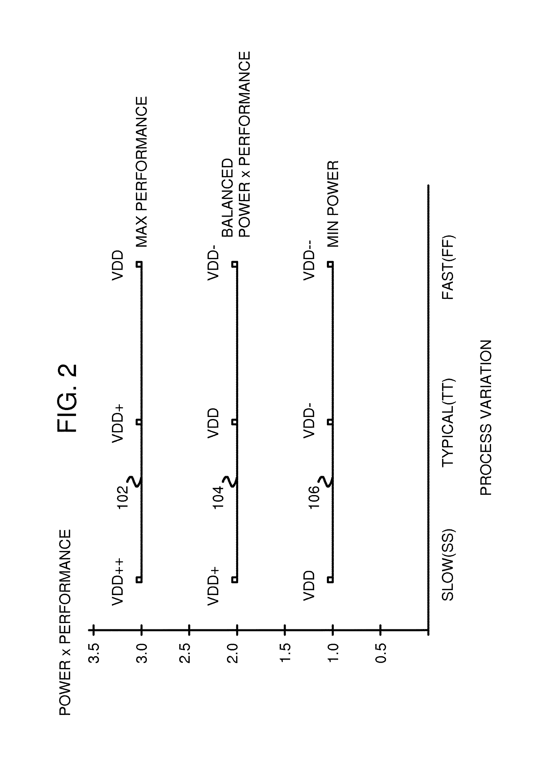
Although the manufacturing process may target a typical device, sometimes process variations produce slower chips or faster chips.
Unfortunately, such process skews are not always reproducible or planned but may occur randomly, making for logistical difficulties.
The fastest process skew (FF) has the highest performance and speed, but also consumes the most power.
This is not optimal, since fast devices are spec'ed slower than they can actually operate, and slow devices actually draw less power than spec'ed.
However, the actual circuit may be much more complex than an oscillator, resulting in tracking errors.

Method used


Image

  • Method and algorithm for functional critical paths selection and critical path sensors and controller insertion
  • Method and algorithm for functional critical paths selection and critical path sensors and controller insertion
  • Method and algorithm for functional critical paths selection and critical path sensors and controller insertion

Examples


Embodiment Construction

[0024]The present invention relates to an improvement in CAD software and IC manufacturing. The following description is presented to enable one of ordinary skill in the art to make and use the invention as provided in the context of a particular application and its requirements. Various modifications to the preferred embodiment will be apparent to those with skill in the art, and the general principles defined herein may be applied to other embodiments. Therefore, the present invention is not intended to be limited to the particular embodiments shown and described, but is to be accorded the widest scope consistent with the principles and novel features herein disclosed.

[0025]The inventors realize that test data patterns can be applied to a dummy path, and slowing of that dummy path can be measured. The measured delay can then be used to adjust added timing margins in other sensors on the chip. The added timing margin accounts for the actual conditions measured.

[0026]For the other t...


PUM


Abstract

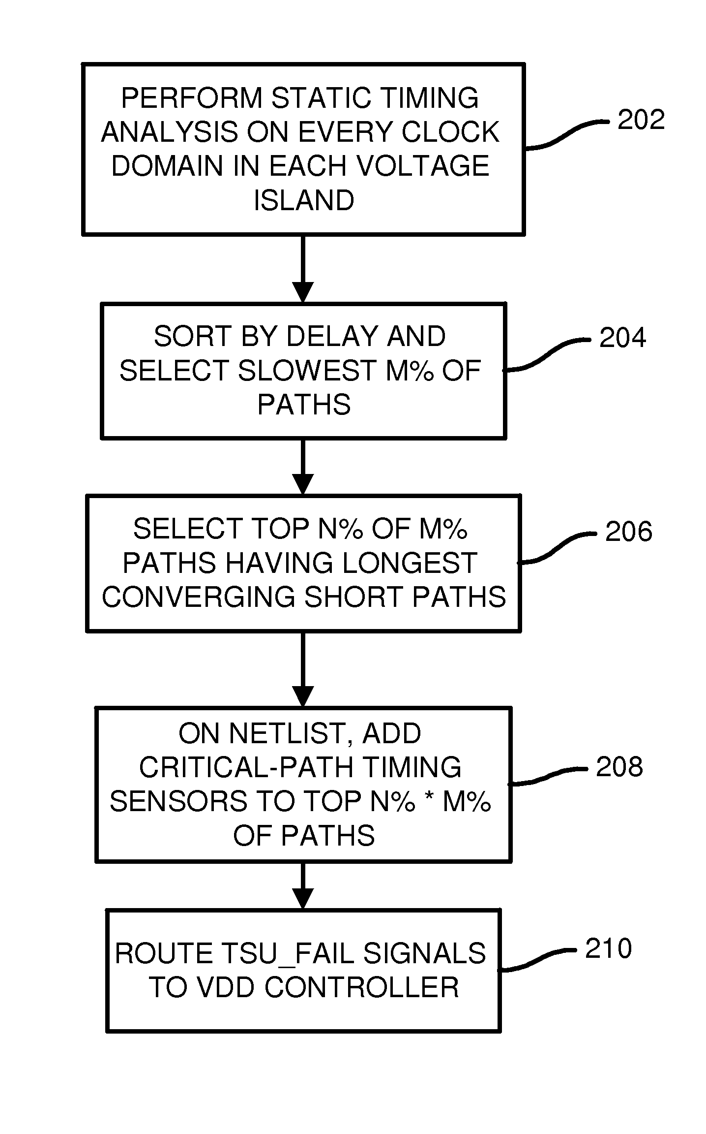
CAD software examines delays of paths in a design from design engineers and first selects the longest paths. Then all paths that converge with these longest paths are examined for delays, and a fastest converging path is selected for each of the longest paths. The longest paths are again sorted by the fastest converging delay, and paths with slower converging paths are selected to be Functional Critical Paths (FCP's). Functional critical path timing sensors are added to each FCP to test setup time with an added margin delay. When the margined path delays fail to meet setup requirements, the functional critical path timing sensors signal a controller to increase VDD. When no failures occur over a period of time, the controller decreases VDD. The CAD software can replicate some of the FCP's and add toggle pattern generators and timing sensors and a margin controller to adjust the margin delay.

Description

RELATED APPLICATION[0001]This application is a non-provisional of the provisional application for “Circuitry and Method for Critical Path Timing Speculation using Edge Sensitive Sampling”. U.S. Ser. No. 62 / 146,412, filed Apr. 13, 2015, and “Computer-Aided Design Software that Selects Functional Critical Paths and Adds CP Sensors and VDD Controller”, U.S. Ser. No. 62 / 183,671, filed Jun. 23, 2015.FIELD OF THE INVENTION[0002]This invention relates to Computer-Aided-Design (CAD), and more particularly to selecting critical paths to connect to added test circuits to measure delays to adjust the power-supply voltage in real-time.BACKGROUND OF THE INVENTION[0003]Semiconductor devices such as Integrated Circuits (IC's), System-On-a-Chip (SOC), or other chips often have millions of transistors. These devices are often designed at a higher level using Register-Transfer-Level (RTL) descriptions that specify logical operation of the chip but do not specify transistors or logic gates. Computer-A...

Claims


Application Information

Patent Timeline
IPC IPC(8): G06F17/50
CPCG06F17/5081G06F17/5072G06F30/3312G06F30/30G06F2119/12G06F2119/06G06F30/398G06F30/392G06F30/3315
Inventor QUINTON, BRADLEYMCCLEMENTS, TRENTHUGHES, ANDREWTANEJA, SANJIV
Owner QUALCOMM INC
Learn More