Safety device for ladders

a safety device and ladder technology, applied in ladders, building construction, construction, etc., can solve the problems of dangerous transfer between a roof and a standard extension ladder, destabilizing the climber, etc., and achieve the effect of easy assembly, easy removal, and easy removal

Active Publication Date: 2017-01-10
ELLIS J NIGEL
View PDF38 Cites 14 Cited by
  • Summary
  • Abstract
  • Description
  • Claims
  • Application Information

AI Technical Summary

Benefits of technology

[0023]Preferably, the distance between the members when mounted on a ladder is from about 23 to 26 inches, permitting a person to easily walk through the safety device while maintain a firm grasp on the safety device.
[0029]The pivot lock plate preferably has two tabs. The first tab (the locking tab) preferably extends perpendicular to the plane of the plate across the smaller face of the sleeve. A tempered spring plate is preferably attached to the inside face of the sleeve to engage the lock plate perpendicular tab to spring bias the lock plate into the original position. The second tab preferably extends upwardly in the plane of the plate. This second tab is preferably used to manually pivot the lock plate from an interference engagement with the ladder top rung when the sleeve is to be removed from the side rail. A triangular side-profiled locking tab cover plate preferably covers the locking tab and spring plate movement and to protect these structures from damage by repeated climbers.
[0030]The labeled safety device left-hand and right-hand members are preferably easily assembled on the side rail ends of a conventional straight or extension ladder and easily removed. The knob operated screw is preferably tightened to remove the slackness when the ladder is in use.

Problems solved by technology

The transfer between a roof and a standard extension ladder is a dangerous task as there is no good way to side step off of a ladder and onto a roof and back which requires walking around the ladder side rails when the OSHA requirement for 30 inch extension is met.
It converts a standard extension ladder or other ladder to enable step through instead of step-around movements, which can be destabilizing for the climber.

Method used


Image

  • Safety device for ladders
  • Safety device for ladders
  • Safety device for ladders

Examples


Embodiment Construction

[0055]The features, advantages and operation of the present invention will become readily apparent and further understood from a reading of this detailed description with the accompanying drawings, in which like numerals refer to like elements, and in which:

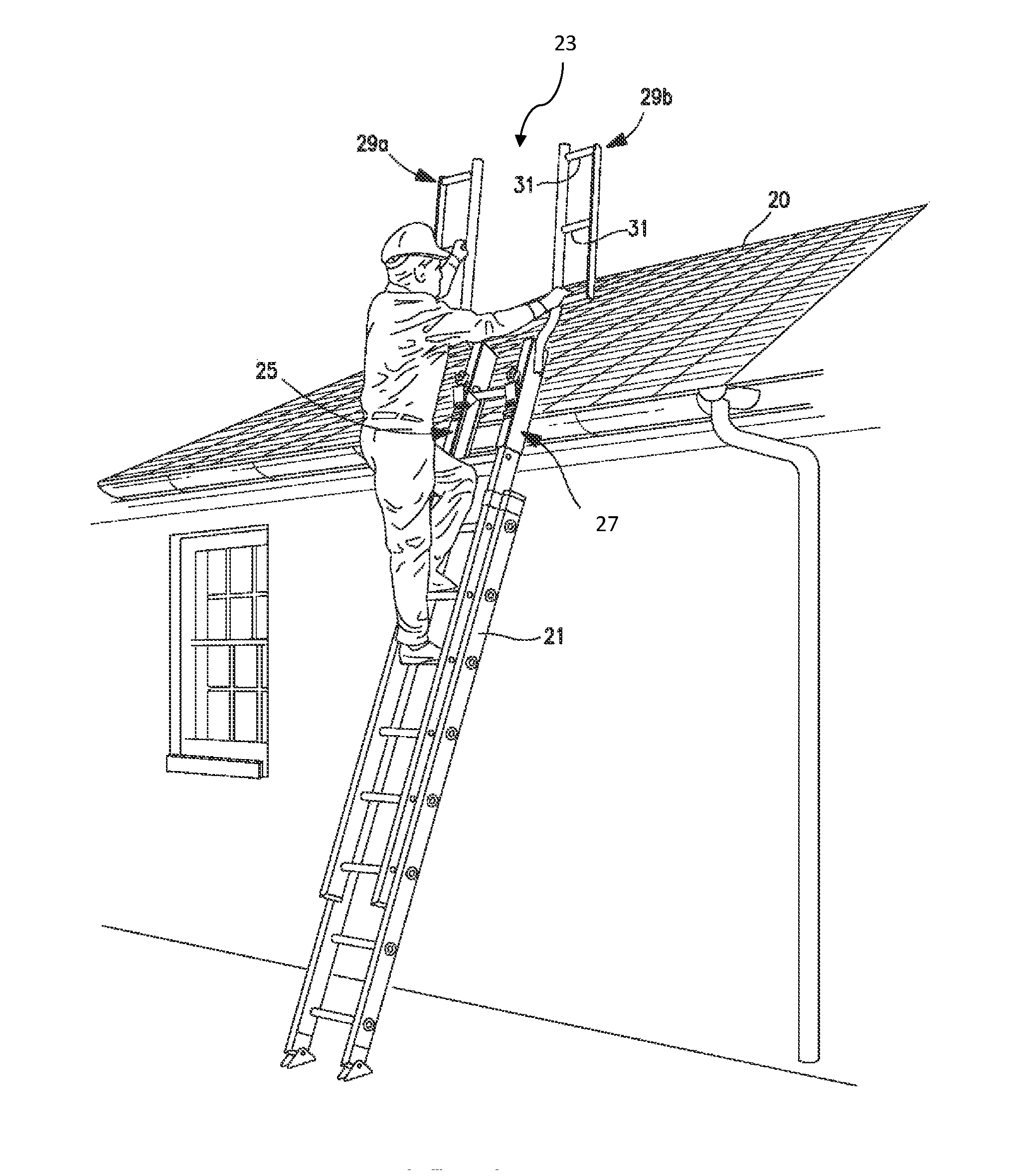
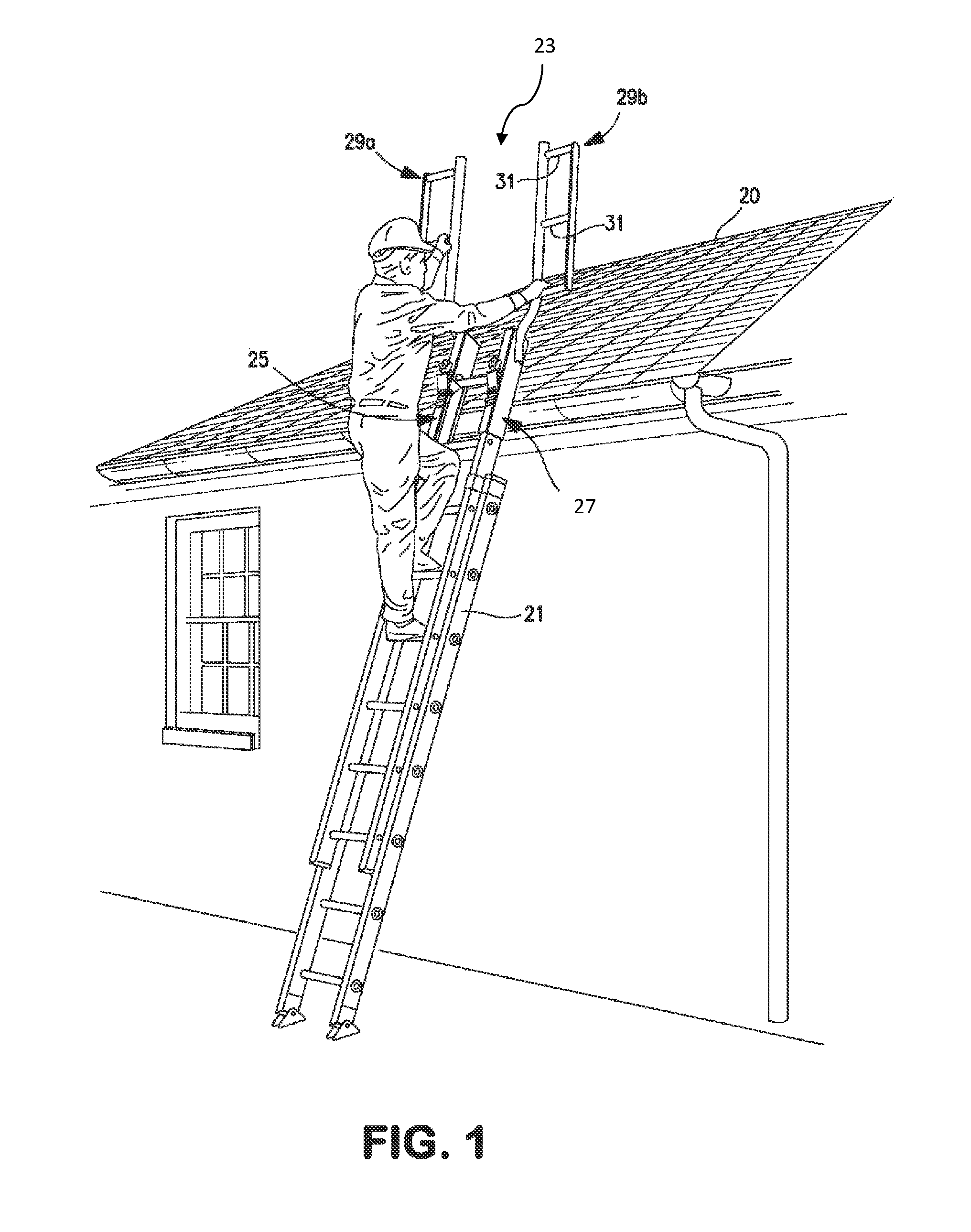
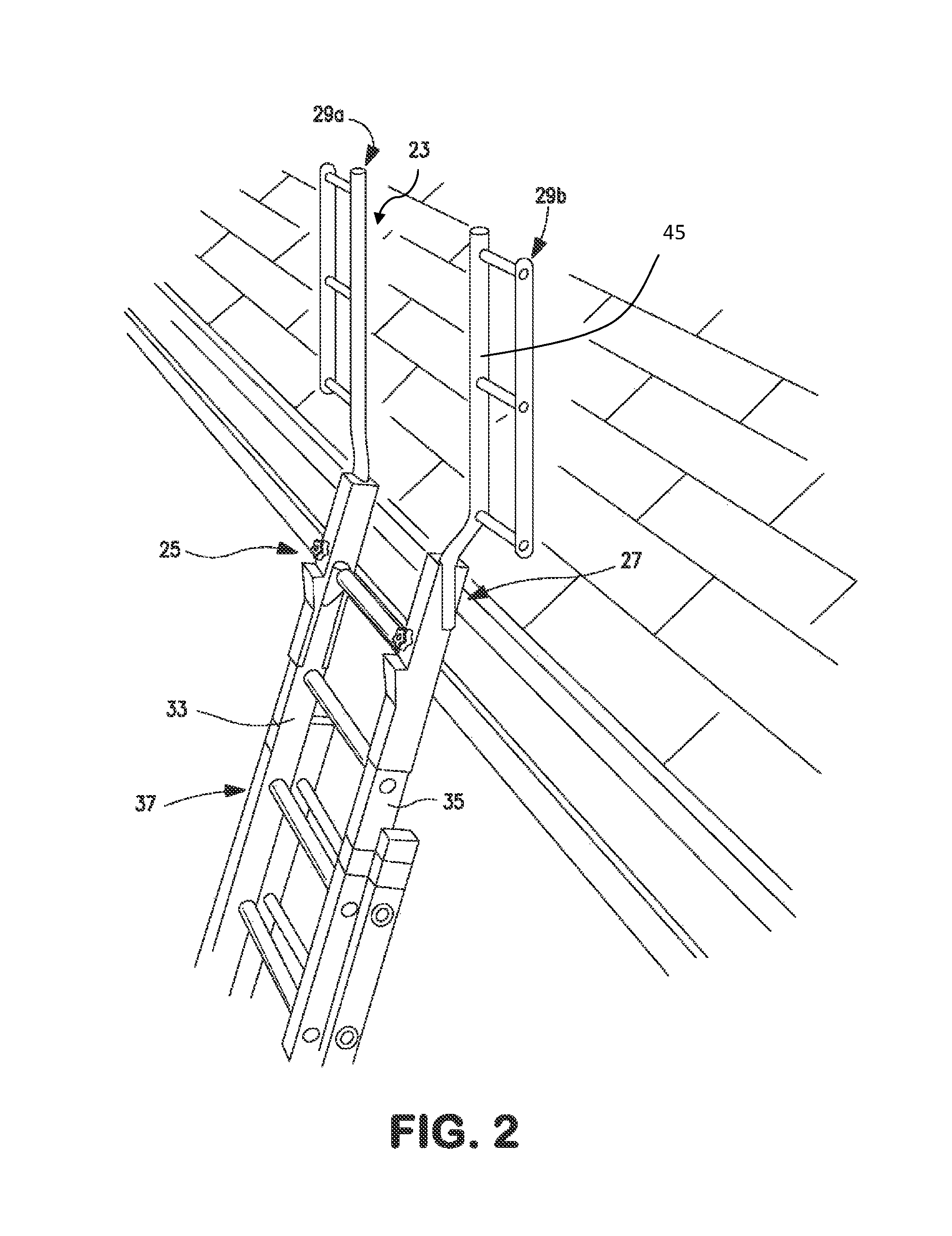
[0056]In one presently preferred embodiment the present invention provides a safety device preferably to be mounted onto the top or distal end of an extension ladder, such as a conventional extension ladder, to add a walk-through configuration having handhold grab framework to the ladder extending vertically above the extension ladder, preferably at the OSHA-recommended distance. The safety device 23 of the present invention can be used with conventional fixed (non-extendable) ladders, conventional extension ladders, articulated (collapsible) ladders, fire rescue ladders, etc.

[0057]The safety device 23 is preferably formed from a high strength material, such as steel or aluminum, and more preferably, a high strength light weight ...


PUM


Abstract

Walk-through safety devices for ladders meeting ANSI and OSHA standards are positioned at the top end of the ladder and are comprised of two, juxtapose-position, mirror image members. One each is mounted on a respective ladder side rail, Each member includes a sleeve (or rectangular tube) which slides down over a respective ladder side rail, a pressure bar which is tightened against the side rail with a knob operated screw, a pivoting engaging lock plate, and a lock plate tab cover plate. A horizontal hand grip framework is held outboard of the ladder side rails vertically upward, being at an angle of about 14.5 degrees upward from the longitudinal axis of the sleeve and side rail when resting against a structure. The framework is held in that position by a flared tube which is bent in two directions.

Description

BACKGROUND OF THE INVENTION[0001]1. Field of the Invention[0002]The present invention relates to safety devices for the upper ends of ladders.[0003]2. Brief Description of the Prior Art[0004]Accidents involving ladders, such as both portable extension ladders and non-extension ladders, can occur when the ladder shifts either because the climber is off balance to one side of the ladder, or because the climber accidentally moves the ladder when climbing off or onto a roof. The most dangerous time when using a ladder to descend is when stepping off of a roof onto a rung of the ladder. The climber is precariously perched, and must cautiously move himself with one foot on the roof and the other on the ladder before bringing the other foot onto the ladder. Standard portable ladders extend above the roof line and the climber must swing step around the extension to exit the ladder.[0005]Additionally, a climber may lose a hand grip or his foot may slip off of a rung, or his foot may engage a...

Claims


Application Information

Patent Timeline
Patent Type & Authority Patents(United States)
IPC IPC(8): E06C7/42E06C7/48E06C7/18E06C1/04E06C7/50
CPCE06C7/182E06C1/04E06C7/183E06C7/48E06C7/50E06C7/486
Inventor ELLIS, J. NIGEL
Owner ELLIS J NIGEL
Why Eureka
Try Eureka