Heat circulation pump

a circulation pump and heat-driven technology, applied in the direction of machines/engines, mechanical equipment, liquid fuel engines, etc., can solve the problems of introducing into the terminal box, and a large part of the heat led through the earthing contact does not get into the terminal box at all, so as to reduce manufacturing and assembly costs

Active Publication Date: 2017-01-10
GRUNDFOS MANAGEMENT AS
View PDF10 Cites 4 Cited by
  • Summary
  • Abstract
  • Description
  • Claims
  • Application Information

AI Technical Summary

Benefits of technology

[0004]Such heating circulation pumps of a small or medium construction type are produced in large-scale manufacture, which is why even the smallest improvements can entail significant savings with regard to manufacture and / or assembly. On the one hand one always strives to technically further improve these pumps and to design them in a more reliable manner, but on the other hand to reduce the manufacturing and assembly costs.
[0006]The basic concept of the solution according to the invention is to arrange the electric connection between the motor-side earthing contact and the plug-side or socket-side earthing contact outside the terminal box, in order in this manner to permit the electrical connection between the earthing contact on the motor housing side and the plug-side or socket-side earthing contact to be able to be led outside the terminal box and at least outside the inside of the terminal box. Such an arrangement has the advantage that the thermal coupling between the motor housing and the terminal box via the earthing which is inherent of the state of the art can be largely avoided, which is particularly advantageous if the motor housing is comparatively warm or comparatively cold compared to the terminal box.
[0012]Advantageously, the contact, in particular the earthing contact is designed as a sheet-metal part which is formed by punching. Such contacts are manufacturable in an inexpensive manner.
[0013]Two or more contacts which are electrically insulated to one another are provided in the plug or in the socket for the connection of the motor. These according to a further development of the invention are constructionally identical to the earthing contact and arranged at a distance to one another and to the earthing contact, wherein the non-earthing contacts also to the motor housing are embedded in plastic which forms a part of the terminal box and / or of the plug or socket. Such a design is particularly advantageous since the same components can be used for the earthing contact as well as for the remaining contacts, which significantly reduces the variety of parts on manufacture and handing, in particular on leading the parts.
[0016]It is particularly advantageous with the application of permanent magnet motors running at high speed, if the terminal box connects on the axial side of the motor housing which is away from the pump housing, since then one can create sufficient space for receiving the motor electronics and specifically essentially independently of the radial and axial extension of the motor, in particular of the stator. With such an axial arrangement of the terminal box, i.e. if the terminal box is arranged on the side of the motor housing which is away from the pump seen in the axial direction of the motor shaft, it is then advantageous to arrange the plug or the socket for the connection on the radial outer side of the motor housing and / or of the terminal box. With the above-mentioned motor construction type, the motor is often design in a slim manner compared to the pump. The pump also comprises suction and pressure nozzle which entail the creation of lateral free spaces which are often not used. It is therefore advantageous to arrange the plug or the socket in this region, since this does not increase the axial construction length of the pump and utilizes spatial regions which are given in any case and which are otherwise not useable. Thereby, it is particularly advantageous to arrange the plug or the socket in a manner displaced to the terminal box, preferably next to the motor housing, and specifically such that the plug direction is parallel to the rotation axis of the motor and pump. This arrangement also has the advantage that no additional free space is required for sticking on the counter-plug or counter-socket, in any case only little radial free space next to the heating circulation pump, which remains free and is unused in any case in practice.
[0017]Thereby, it is advantageous to not only design the electrical connections between the terminal box and the motor or between the plug and / or socket and the connection cable as a plug-in connection, but moreover also the mechanical connection between the terminal box and the motor and / or pump housing. This can be effected by way of at least one snap connection being provided between these components, wherein the joining direction of the snap connection corresponds to the joining direction of the earthing contact. The terminal box can be stuck on without any tools due to this design according to the invention, wherein simultaneously all necessary electrical connections between the motor and terminal box are closed with this sticking-on. Such an arrangement is particularly advantageous with large-scale manufacture, since it simplifies and cheapens the assembly.

Problems solved by technology

The heat which is introduced into the terminal box from the motor housing via the earthing contact however is significantly lower than with known designs, since a branching of the heat flows also occurs due to the branching outside the terminal box or within the terminal box wall, so that a greater part of the heat led via the earthing contact does not get into the terminal box at all given a suitable design.

Method used


Image

  • Heat circulation pump
  • Heat circulation pump
  • Heat circulation pump

Examples


Embodiment Construction

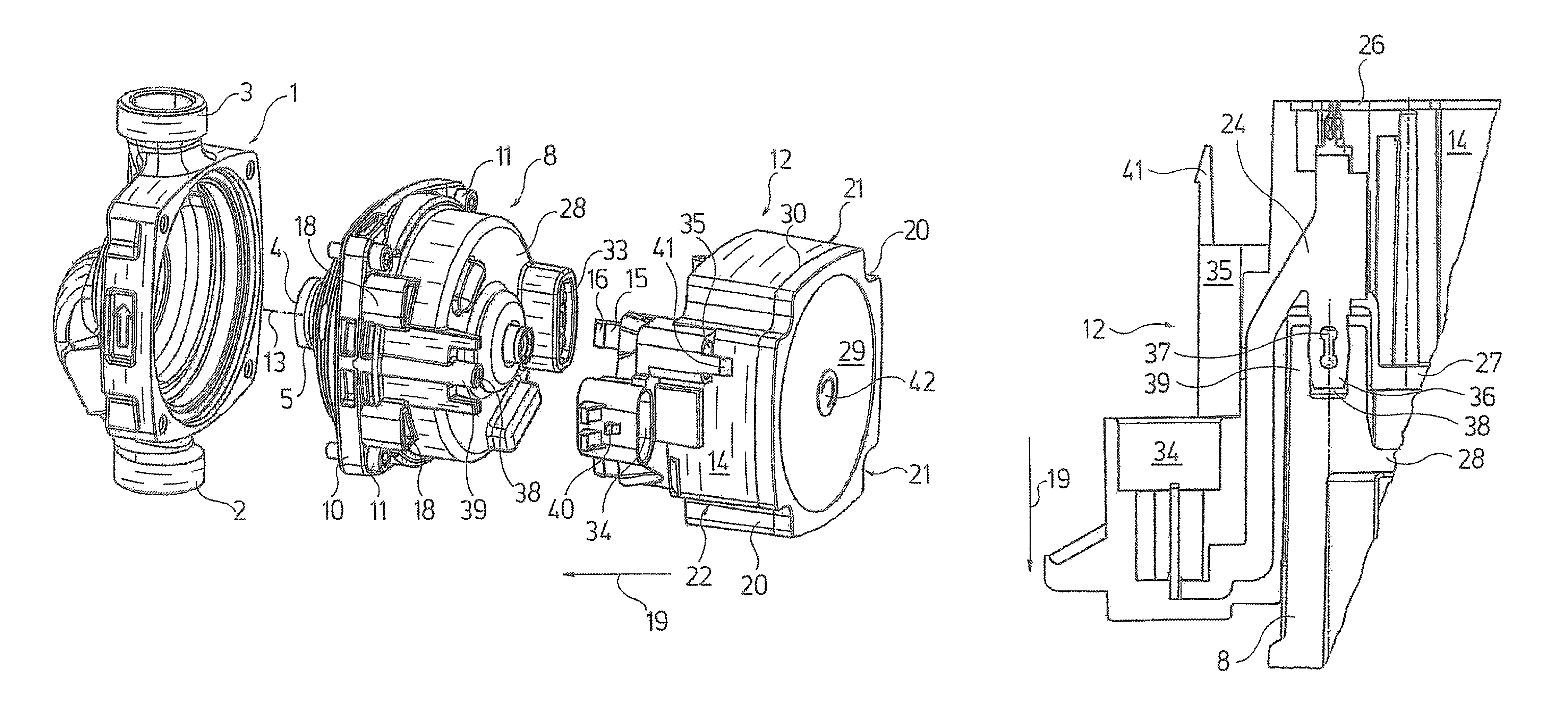
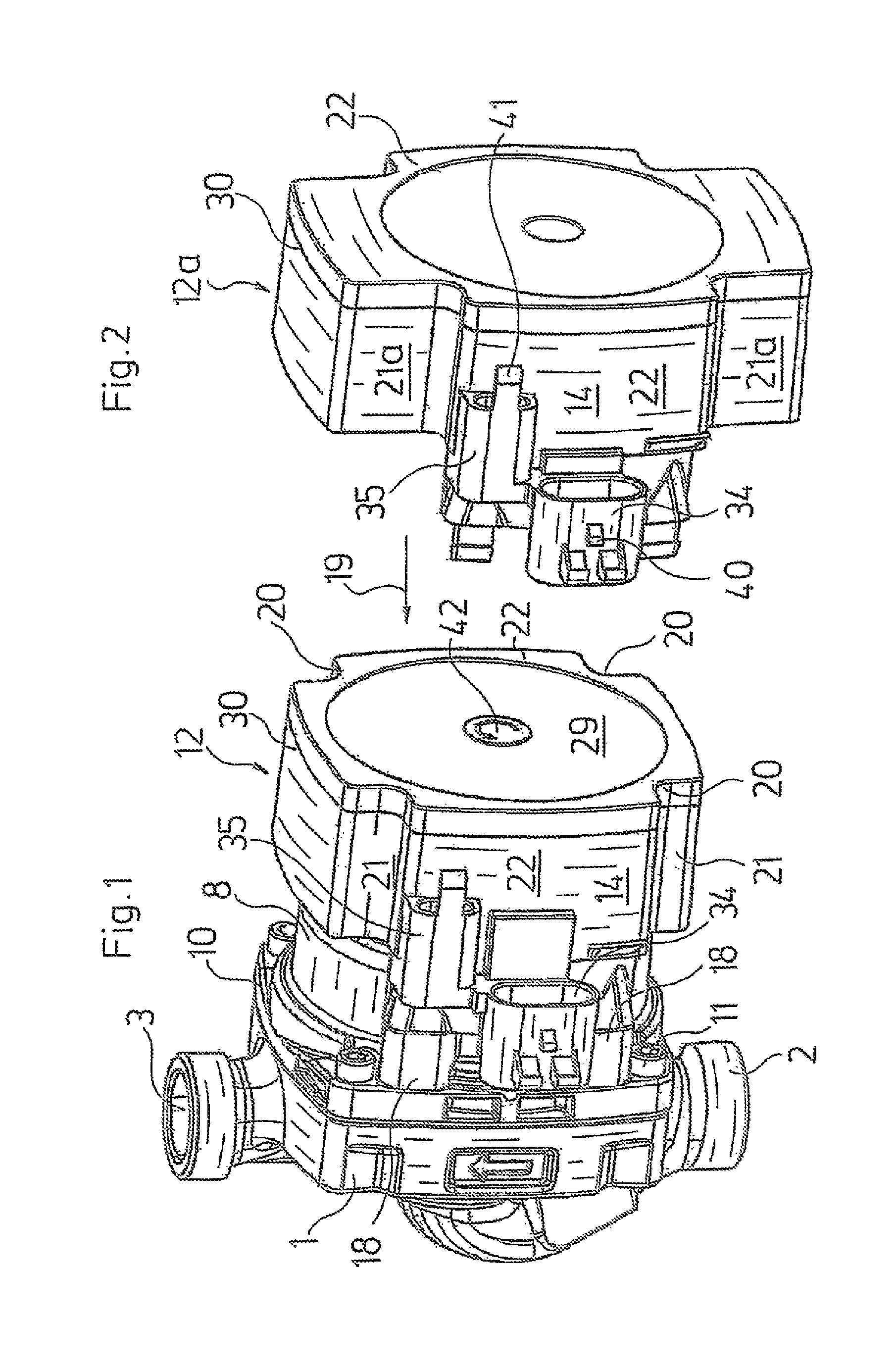
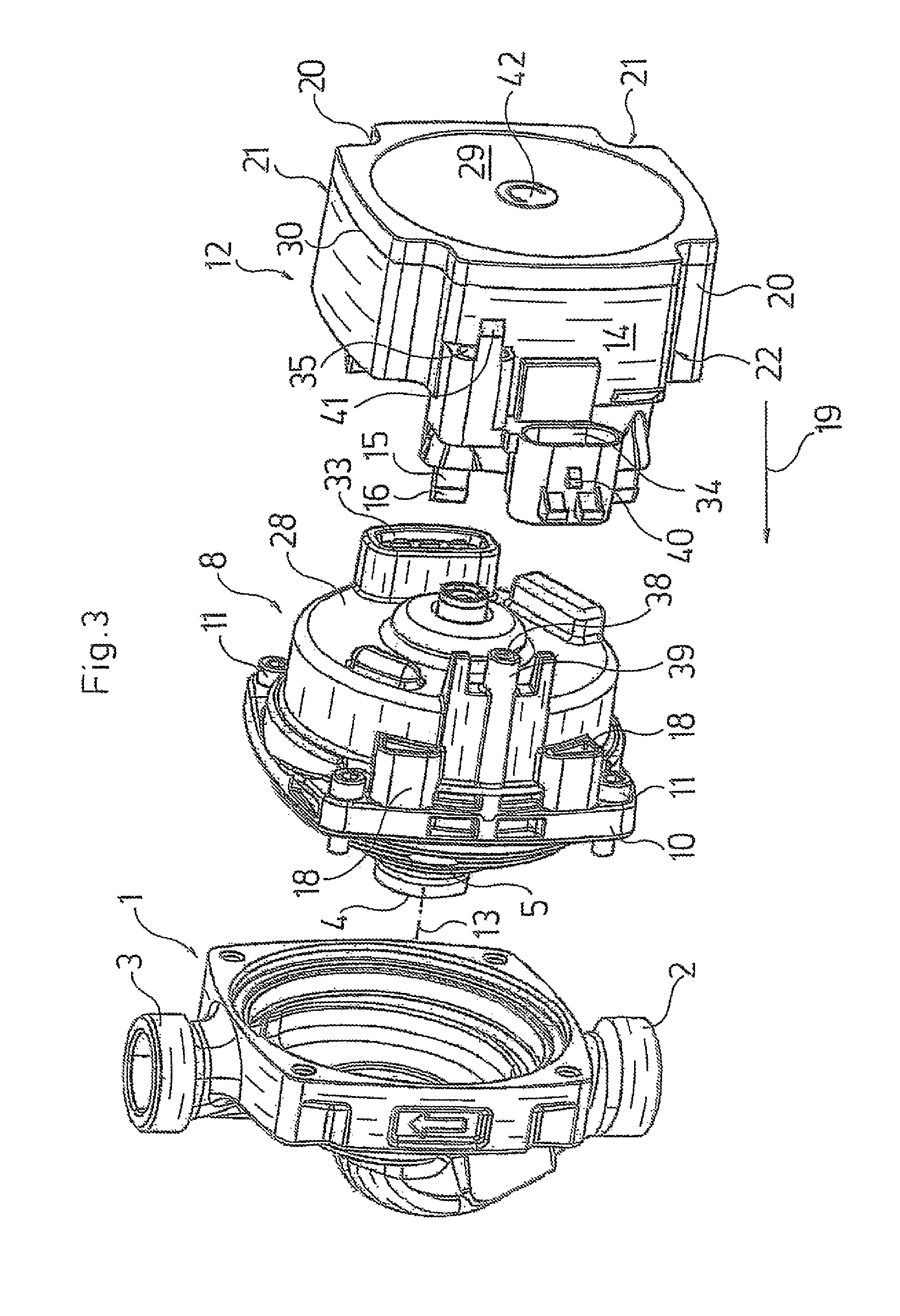
[0030]Referring to the drawings in particular, the heating circulation pump represented by way of FIGS. 1, 3 and 8 comprises a centrifugal pump with a pump housing 1 with a suction nozzle 2 and with a pressure nozzle 3 with a channel guidance formed therebetween which leads the fluid coming from the suction nozzle 2 to a suction port 4 of a pump impeller 5 which is mounted within the pump housing 1 and whose driven side connects to a channel leading to the pressure nozzle 3.

[0031]The heating circulation pump moreover comprises a motor, here a wet-running motor, whose rotor 6 runs in a can 7 which is filled with fluid. The can 7 is surrounded by a stator, i.e. by the motor windings arranged around the can 7 on the peripheral side, as well as by a motor housing 8 receiving the stator. The rotor 6 comprises a central shaft 9 which extends to into the pump housing 1 and carries the pump impeller 5, so that the rotational movement of the rotor 6 is transmitted onto the pump impeller 5.

[0...


PUM


Abstract

A heat circulation pump includes a pump housing (1) with a pump impeller driven by an electric motor. The electric motor is arranged in a motor housing (8) connected to the pump housing (1). A plastic terminal box (12) is fixed to the motor housing (8) and houses electric and / or electronic components of the engine control and electrically connects the motor, a ground contact arranged on the motor housing (8), and a plug or a socket (34) arranged on the outside of the terminal box (12). The ground contact arranged on the motor housing is connected in an electrically conductive manner to a ground contact of the plug or socket (34) and to at least one conductor inside the terminal box (12). The electric connection between the ground contact arranged on the motor housing (8) and the ground contact of the plug or socket (34) is arranged outside of the terminal box (12).

Description

CROSS REFERENCE TO RELATED APPLICATIONS[0001]This application is a United States National Phase Application of International Application PCT / EP2012 / 053221 filed Feb. 24, 2012 and claims the benefit of priority under 35 U.S.C. §119 of European Patent Application EP 11002072.4 filed Mar. 12, 2011, the entire contents of which are incorporated herein by reference.FIELD OF THE INVENTION[0002]The invention relates to a heating circulation pump with a pump housing, with a pump impeller arranged therein and which is driven by an electric motor arranged in a motor housing connected to the pump housing. A terminal box of plastic is fastened on the motor housing and is for receiving electrical and / or electronic components of the motor control as well as for the electrical connection of the motor, with an earthing (ground) contact arranged on the motor housing and with a plug or socket of an electric plug-in connection for the electric connection. The plug or socket is arranged at the outside ...

Claims


Application Information

Patent Timeline
Patent Type & Authority Patents(United States)
IPC IPC(8): H02K5/22F04D29/02F04D13/06F04D29/42F04D29/58H02K5/10H02K7/14H02K5/128
CPCH02K5/225F04D13/06F04D13/0606F04D13/0686F04D13/0693F04D29/026F04D29/426F04D29/5893H02K5/10H02K5/128H02K7/14H02K11/33F05D2300/10F05D2300/43F04D13/0626
Inventor HOJ, FINN MATHIESENBLAD, THOMAS
Owner GRUNDFOS MANAGEMENT AS
Why Eureka
Try Eureka