Glenoid implant anchor post

a technology of glenoid and humerus, which is applied in the field of glenoid implant anchor posts, can solve the problems of requiring repair or replacement, affecting the interaction between the glenoid and the humerus, and assembly failure, and achieves the effect of convenient customization

Active Publication Date: 2017-01-17
HOWMEDICA OSTEONICS CORP
View PDF17 Cites 18 Cited by
  • Summary
  • Abstract
  • Description
  • Claims
  • Application Information

AI Technical Summary

Problems solved by technology

In an unhealthy shoulder joint, the interaction between the glenoid and the humerus are compromised, requiring repair or replacement.
Due to difficulties in designing a mechanism to lock the two pieces together, the assembly can fail over time.
Replacement of the glenoid component requires that the patient undergo an additional surgical procedure and be subjected to additional recovery time and costs.

Method used


Image

  • Glenoid implant anchor post
  • Glenoid implant anchor post
  • Glenoid implant anchor post

Examples


example 1

Insertion

[0072]FIG. 11 illustrates the load versus displacement of a glenoid component of the present invention and the load versus displacement of a comparative glenoid component during insertion into a foam structure designed to exhibit similar density properties of a scapula. The foam structure included an anchor hole for accepting an anchor of the glenoid component of the present invention and an anchor of the comparative glenoid component.

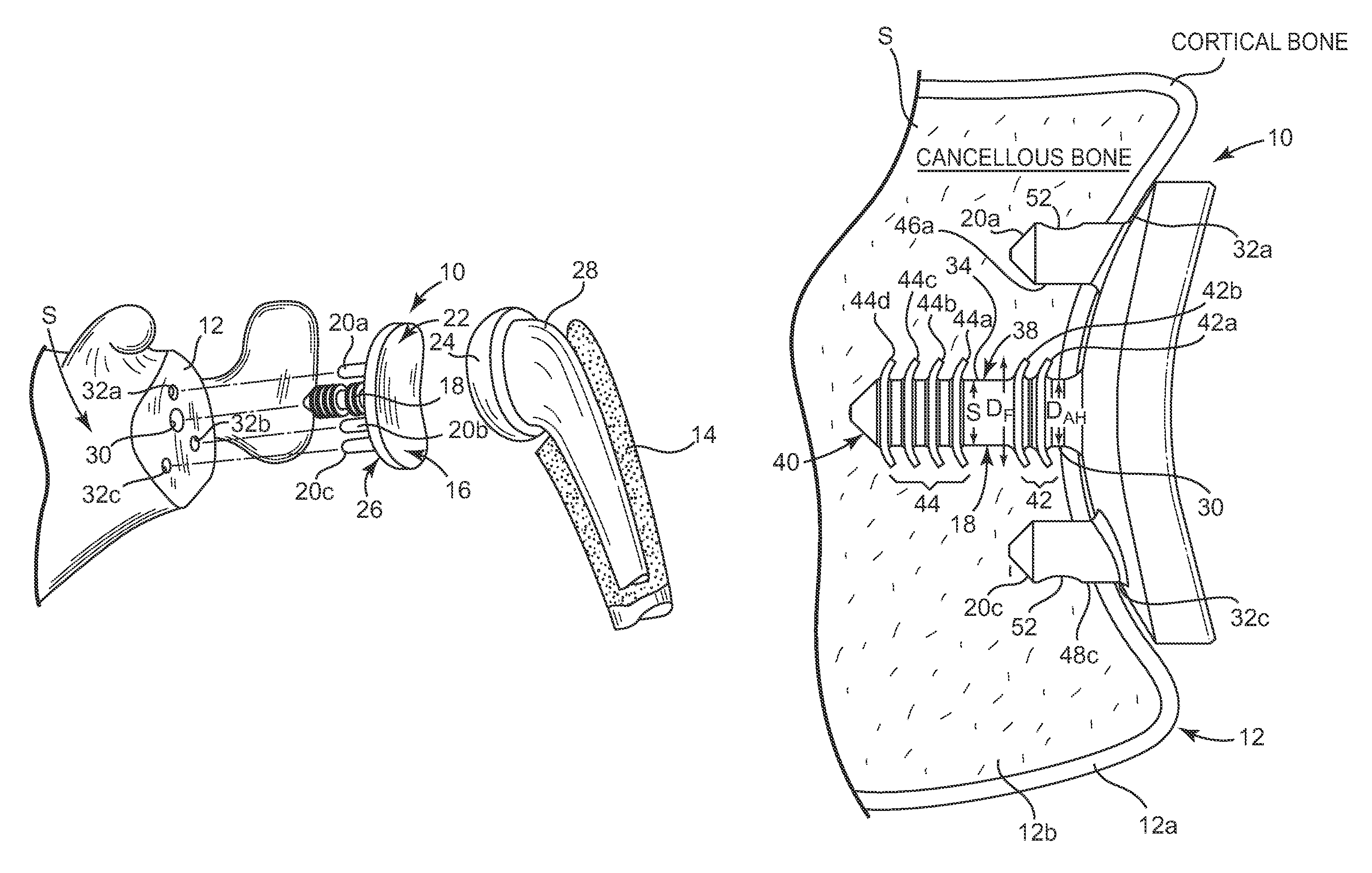
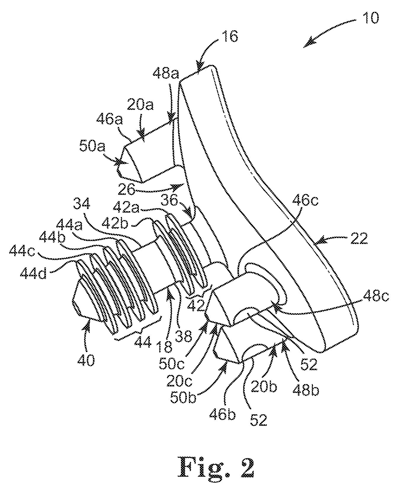
[0073]The glenoid component of the present invention included an anchor having a set of four distal fins extending from a distal end of the anchor and a set of two proximal fins extending from a proximal end of the anchor. The set of distal fins and the set of proximal fins are separated by a middle section of the anchor, such as illustrated in FIG. 2. The set of proximal fins were offset from a rear surface of the head portion by about 2.5 millimeters.

[0074]The comparative glenoid component was substantially similar to the glenoid component o...

example 2

Removal

[0078]FIG. 12 illustrates the load versus displacement of the glenoid component of the present invention and the load versus displacement of the comparative glenoid component during removal from the foam structure.

[0079]As can be seen in FIG. 12, the initial force required to pull the glenoid component of the present invention out from the foam structure spiked to about 39 pounds in the first millimeter of displacement, followed immediately by a spike of about 43.5 pounds at about 2 millimeters of displacement. In particular, a force of about 39 pounds was required to pull the first proximal fin through the anchor hole and a force of about 43.5 pounds was required to pull the second proximal fin through the anchor hole. These spikes all occurred within about 2 millimeters of displacement of the glenoid component of the present invention.

[0080]By contrast, the initial force required to move the comparative glenoid component relative to the foam structure increased more gradual...


PUM


Abstract

A prosthesis that mechanically couples with both cancellous bone and cortical bone of a glenoid includes a head portion comprising a rear surface and an articular surface, an anchor member, and a plurality of deformable fins extending radially outward from the anchor member. The anchor member includes a distal end and a proximal end connected to the rear surface of the head portion. The plurality of deformable fins extend radially outward from the anchor member and includes at least a first proximal fin adjacent to the rear surface of the head portion positioned to engage with the cortical bone. The anchor member may also include at least one distal fin located proximate the distal end of the anchor member positioned to engage with the cancellous bone.

Description

TECHNICAL FIELD[0001]The present invention relates generally to an apparatus and device for securing a glenoid implant to a glenoid, and in particular, to an anchor with deformable portions that are adapted to form a cement-less connection with the glenoid.BACKGROUND OF THE INVENTION[0002]In a healthy shoulder joint, the humeral head of the humerus interacts with the glenoid of the scapula to form a “ball and socket” joint. The humeral head abuts and articulates with the glenoid to allow a wide range of motion in the shoulder. In an unhealthy shoulder joint, the interaction between the glenoid and the humerus are compromised, requiring repair or replacement. Total shoulder replacement is one method used to replace shoulder joints that have been damaged beyond repair due to trauma or disease. Typically, a total shoulder replacement procedure includes providing a glenoid component and a humeral component that interact with each other at an articulating surface.[0003]Conventionally, gl...

Claims


Application Information

Patent Timeline
Patent Type & Authority Patents(United States)
IPC IPC(8): A61F2/40A61F2/30
CPCA61F2/4081A61F2002/30604A61F2002/30822A61F2002/30828A61F2002/30878A61F2002/30881A61F2002/30892A61F2002/30897A61F2002/30884
Inventor COURTNEY, JR., ROBERTMUTCHLER, AUSTIN W.CHURCHILL, R. SEAN
Owner HOWMEDICA OSTEONICS CORP
Why Eureka
Try Eureka