Latency-based power mode units for controlling power modes of processor cores, and related methods and systems

a technology of power mode units and processor cores, applied in the field of processor cores, can solve the problems of control unit power collapse of the processor core, the processing instructions within the processor core contribute to the overall power consumption of the corresponding cpu, so as to reduce the power consumed by the processor core, conserve power, and save power

Inactive Publication Date: 2017-01-24
QUALCOMM INC
View PDF14 Cites 0 Cited by
  • Summary
  • Abstract
  • Description
  • Claims
  • Application Information

AI Technical Summary

Benefits of technology

[0007]A thread is in pending status in a processor core when the processing of an instruction in the thread consists of waiting for data to be retrieved from outside of the processor core for the instruction without the thread otherwise processing another instruction. For example, an operand of an instruction being processed by a thread may be data in memory located outside of the processor core. If the processor core does not require as much power to operate while a thread is in pending status and waiting for a request from outside of the processor core, the power consumed by the processor core can also be reduced during the latency of these waiting periods. In this manner, power can be conserved in the processor core even when threads are in pending status. A central processing unit (CPU) being able to additionally conserve power when threads are in pending status, as opposed to only when all threads are inactive, can reduce the overall power consumption in the processor core and its corresponding CPU.

Problems solved by technology

In this regard, processing instructions within a processor core contributes to the overall power consumption of the corresponding CPU.
However, if no threads are in active status in a processor core, the power control unit may power collapse the processor core to conserve power.

Method used


Image

  • Latency-based power mode units for controlling power modes of processor cores, and related methods and systems
  • Latency-based power mode units for controlling power modes of processor cores, and related methods and systems
  • Latency-based power mode units for controlling power modes of processor cores, and related methods and systems

Examples


Embodiment Construction

[0020]With reference now to the drawing figures, several exemplary aspects of the present disclosure are described. The word “exemplary” is used herein to mean “serving as an example, instance, or illustration.” Any aspect described herein as “exemplary” is not necessarily to be construed as preferred or advantageous over other aspects.

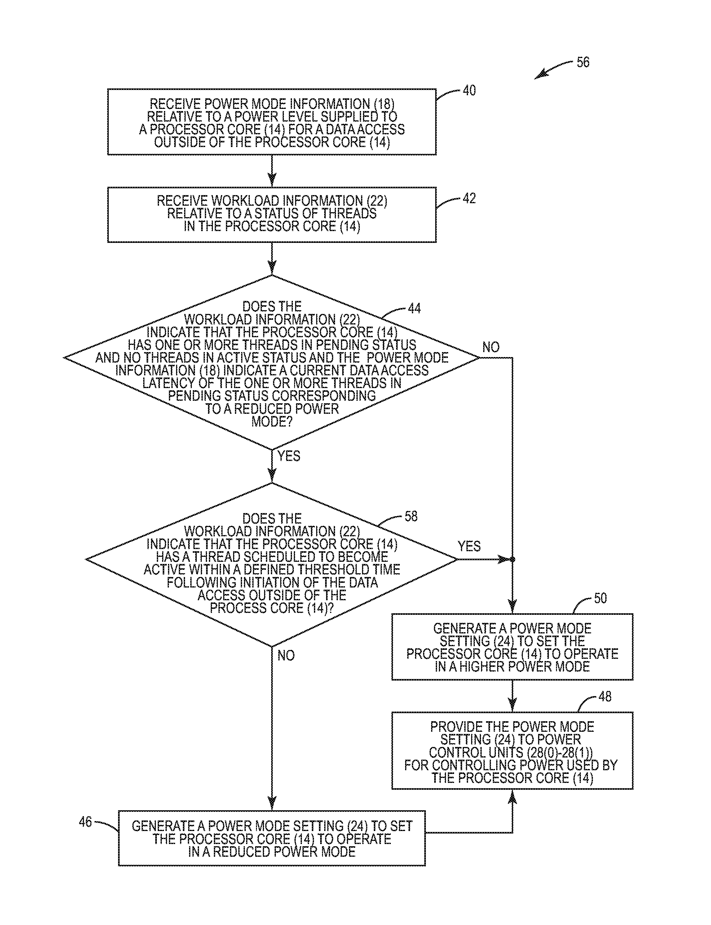
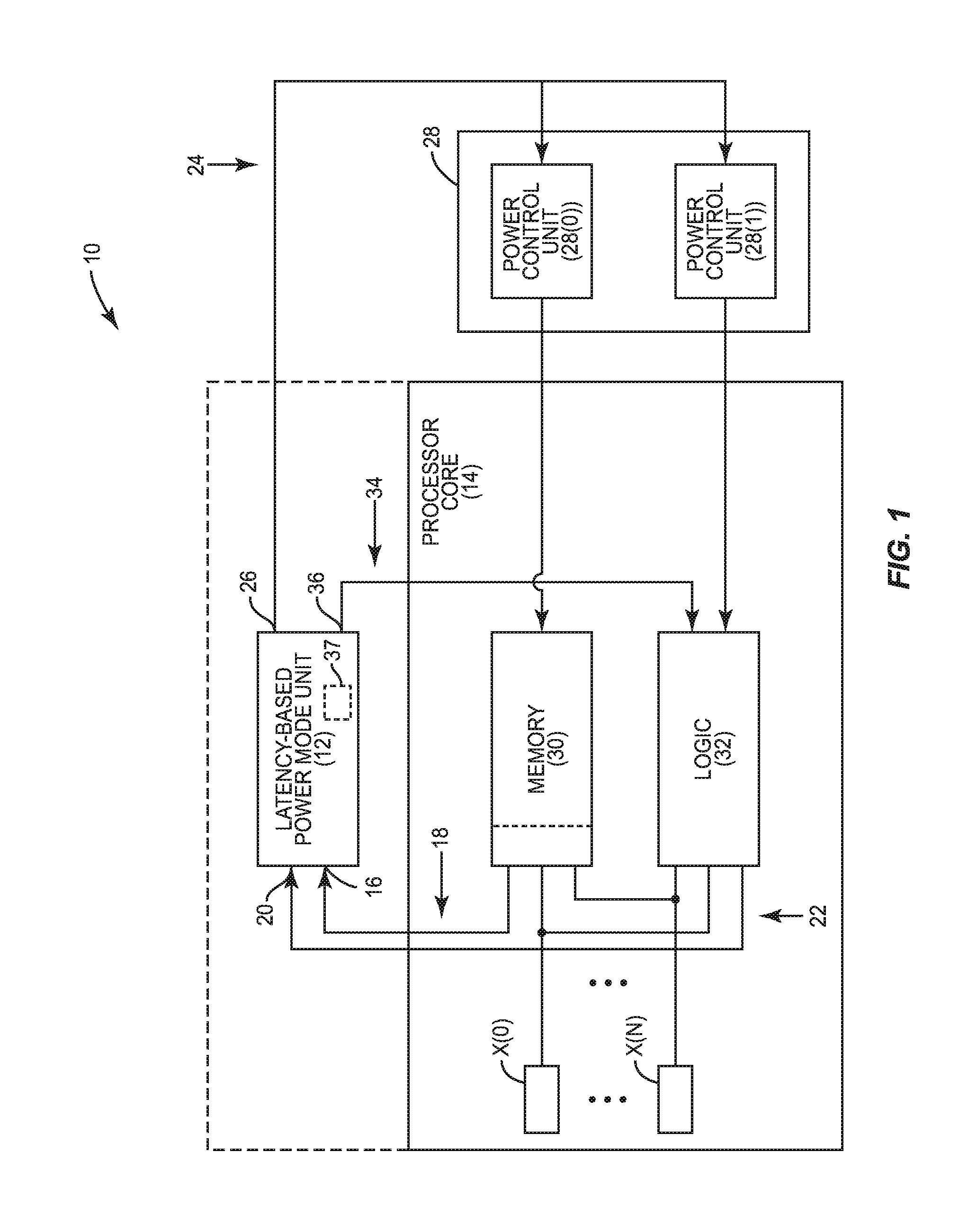
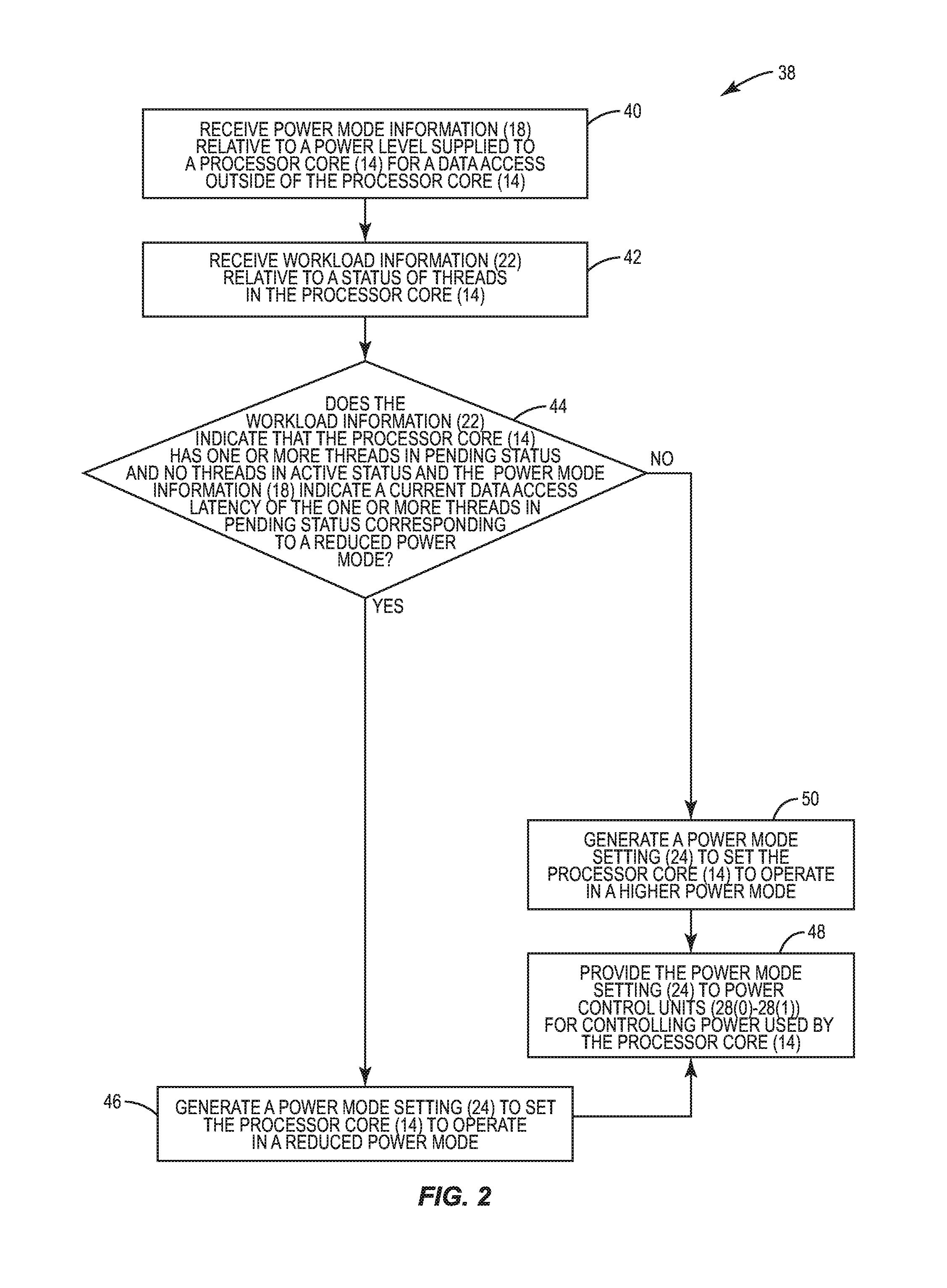
[0021]Aspects disclosed herein include latency-based power mode units for controlling power modes of processor cores. Related methods and systems are also disclosed. In this regard, FIG. 1 illustrates an exemplary central processing unit (CPU) subsystem 10 employing an exemplary latency-based power mode unit 12 for controlling a power mode of a processor core 14. The processor core 14 has a plurality of threads X(0)-X(N) that are each configured to provide concurrent processing, where ‘N+1’ is equal to the number of threads. However, the processor core 14 could include only one (1) thread. As discussed in more detail below, the latency-based power mod...


PUM


Abstract

Latency-based power mode units for controlling power modes of processor cores, and related methods and systems are disclosed. In one aspect, the power mode units are configured to reduce power provided to the processor core when the processor core has one or more threads in pending status and no threads in active status. An operand of an instruction being processed by a thread may be data in memory located outside processor core. If the processor core does not require as much power to operate while a thread waits for a request from outside the processor core, the power consumed by the processor core can be reduced during these waiting periods. Power can be conserved in the processor core even when threads are being processed if the only threads being processed are in pending status, and can reduce the overall power consumption in the processor core and its corresponding CPU.

Description

BACKGROUND[0001]I. Field of the Disclosure[0002]The technology of the disclosure relates generally to processor cores, and particularly to controlling power modes of processor cores.[0003]II. Background[0004]Processor-based computer systems can include one or more central processing units (CPUs) that each includes one or more processor cores for instruction execution. Each processor core includes hardware resources used to process an instruction through multiple pipeline stages. For example, processing an instruction in a pipeline may include fetching the instruction and decoding the instruction prior to sending the instruction to an execution unit, such as an arithmetic logic unit. Further, hardware resources of a processor core can be divided into separate portions known as “threads,” also referred to as “hardware threads.” The threads provide the processor core with the ability to process multiple instructions concurrently in parallel. More specifically, a thread within a process...

Claims


Application Information

Patent Timeline
Patent Type & Authority Patents(United States)
IPC IPC(8): G06F1/32G06F9/48
CPCG06F1/3203G06F1/3206G06F1/3243G06F1/3296G06F9/48Y02B60/1239G06F1/3228G06F9/4893Y02D10/00
Inventor VENKUMAHANTI, SURESH KUMARSASSONE, PETER GENEPATIL, SANJAY BHAGAWAN
Owner QUALCOMM INC
Why Eureka
Try Eureka