
Optical frequency domain reflectometry (OFDR) system

a technology of optical frequency domain and reflectometry, which is applied in the field of optical analysis, can solve the problems of reducing the effective rate at which the measurement process can be reliably repeated, affecting reliability, and weakening the strength of the interference signal coming from these certain parts of the sensing fiber

Active Publication Date: 2017-01-24
KONINKLJIJKE PHILIPS NV
View PDF14 Cites 2 Cited by
  • Summary
  • Abstract
  • Description
  • Claims
  • Application Information

AI Technical Summary

Benefits of technology

This approach enables faster and more accurate OFDR measurements by eliminating the need for separate measurements and reducing errors caused by environmental changes, while maintaining high reliability and accuracy.

Problems solved by technology

Consequently, the strength of the interference signal coming from these certain parts of the sensing fiber will be very low.
The length of the intermediate measurement time between the first measurement and the second measurement may, however, in some situations negatively affect the reliability of the result.
Similarly, the dependency on two measurements rather than a single measurement can also reduce the effective rate at which the measurement process can be reliably repeated, e.g. if one measurement (i.e. a scan) is corrupt, due e.g. a wrong detector signal, the wavelength calibration and / or linearization could be incorrect or unusable, then the entire measurement process must be repeated.

Method used


Image

  • Optical frequency domain reflectometry (OFDR) system
  • Optical frequency domain reflectometry (OFDR) system
  • Optical frequency domain reflectometry (OFDR) system

Examples


embodiment (

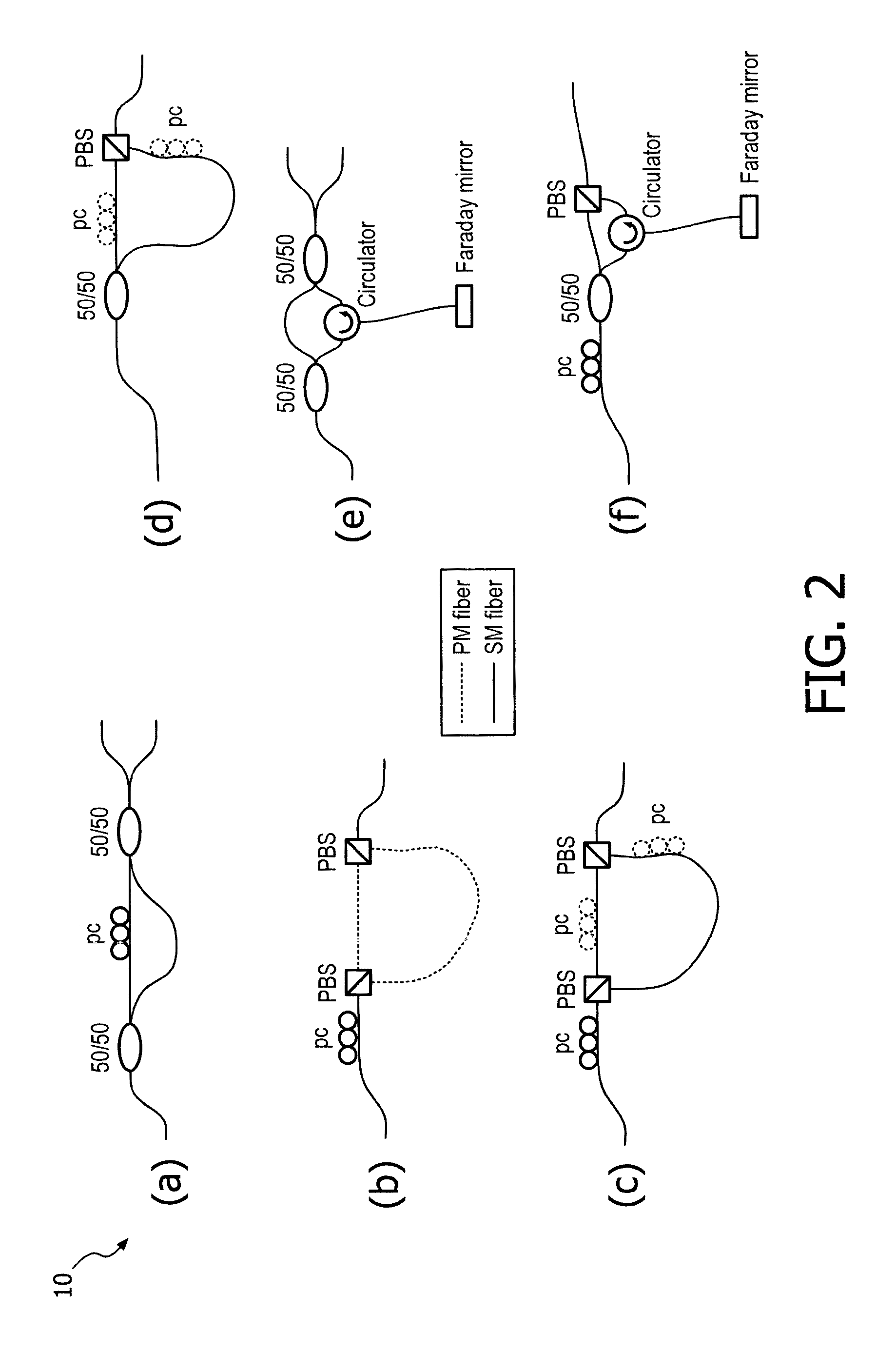
[0085c) is similar to embodiment (b), but in embodiment (c) standard single-mode fibers are used for the two branches. As these fibers are not guaranteed to maintain polarization, the polarization states of the two branches upon arrival at the combining PBS may no longer be linear and aligned with the polarization axes of the combiner PBS. Although the combiner PBS cleans up the polarization states of the light coming from the two branches so that linear, orthogonal, states end up in the output fiber, power may be lost. To minimize power losses, the two branches can be equipped with polarization controllers (shown dotted in the Figure).

[0086]Embodiment (d) has a 50 / 50 splitter as its splitting element to divide the light over the two branches. Standard single-mode fibers are used for the two branches. Embodiment (d) uses a PBS as a combiner, thus ensuring that the polarization states of the two branches always result in two linearly polarized orthogonal states in the output. The opt...


PUM


Abstract

There is presented an optical frequency domain reflectometry (OFDR) system (100) comprising a first coupling point (15) arranged for splitting radiation into two parts, so that radiation may be emitted into a reference path (16) and a measurement path (17). The system further comprises an optical detection unit (30) capable of obtaining a signal from the combined optical radiation from the reference path and the measurement path via a second coupling point (25). The measurement path (17) comprises a polarization dependent optical path length shifter (PDOPS, PDFS, 10), which may create a first polarization (PI) and a second polarization (P2) for the radiation in the measurement path, where the optical path length is different for the first and second polarizations in the measurement path. This may be advantageous for obtaining an improved optical frequency domain reflectometry (OFDR) system where e.g. the two measurements for input polarizations may be performed in the same scan of a radiation source.

Description

CROSS-REFERENCE TO PRIOR APPLICATIONS[0001]This application is the U.S. National Phase application under 35 U.S.C. §371 of International Application Serial No. PCT / EP2013 / 069083, filed on Sep. 16, 2013, which claims the benefit of EP Application Serial No. 12188515.6, filed on Oct. 15, 2012. These applications are hereby incorporated by reference herein.FIELD OF THE INVENTION[0002]The present invention relates to systems for optical analysis, more particularly the present invention relates to an optical frequency domain reflectometry (OFDR) system and a method for a method for obtaining optical frequency domain reflectometry data.BACKGROUND OF THE INVENTION[0003]In Optical Frequency Domain Reflectometry (OFDR), light from a tunable laser source is coupled into a measurement fiber, or more generally, a device under testing (DUT), and the reflected or backscattered light is made to interfere with light from the same source that has traveled along a reference path yielding information ...

Claims


Application Information

Patent Timeline
Patent Type & Authority Patents(United States)
IPC IPC(8): H04B10/071G01M11/00H04B10/25
CPCH04B10/071G01M11/3172G01M11/3181H04B10/25G01B11/18
Inventor HORIKX, JEROEN JAN LAMBERTUS'T HOOFT, GERT WOMARELL, MILAN JAN HENRI
Owner KONINKLJIJKE PHILIPS NV
Learn More