Door closer capable of adjusting its closing speed

a technology of door closer and closing speed, which is applied in the direction of door/window fittings, wing openers, constructions, etc., can solve the problems of increasing maintenance service costs and oil spilling risk, and achieve the effect of reducing costs and maintenance service fees and eliminating oil spilling contamination

Active Publication Date: 2017-01-31
CMECH (GUANGZHOU) INDUSTRIAL LTD
View PDF27 Cites 11 Cited by
  • Summary
  • Abstract
  • Description
  • Claims
  • Application Information

AI Technical Summary

Benefits of technology

[0013]there is a gap between the second side wall and an inner side wall of the sliding rail, the second side wall is inclined from bottom of the groove, such that air enters the hermetic chamber through the first air intake and the gap when the piston slides towards left side, the air in the hermetic chamber is then compressed and the seal ring seals the gap, and thereby the air could be exhausted only by a regulating valve. Therefore, the counteraction to the piston could be adjusted by adjusting the exhaust of the regulating valve, and thereby the sliding speed of the sliding block could be adjusted.
[0015]Furthermore, the pulley is a cam, and the driving components comprises a driving piston configured at one end of the spring, and a cam roller on the driving piston; the cam roller is tangent to the profile of the cam; the intersection of the cam roller and the cam deviates from a line from the center of the cam roller to the shaft of the cam; the other end of the spring is connected with a side wall of the receiving chamber, the profile of the cam is designed to balance the varied resilience of the spring, such that the door is closed uniformly. Further, in order to close the door eventually, it can ensure there is a sufficient thrust to the door being locked at the last moment.
[0023](2) The driving structure is formed by the cam and the spring, when the door starts closing, the spring possesses a great resilience, but when the door almost close completely, the spring possesses a small resilience. The closing force can be adjusted by the profile of the cam as the resilience of the spring is varied all the way, thus the door is closed uniformly. In addition, it can ensure there is a sufficient thrust to the door being locked eventually, and eliminates the risk of hitting people getting through the door.
[0024](3) The following uses air for controlling, this reduces the cost and the maintenance service fee, and eliminates the contamination of oil spilling.

Problems solved by technology

A much longer closing time can cause many problems, for example, the cold air in winter can enter the house easily, or a security flaw will appear.
Moreover, it is difficult for users to adjust the door closer, the above flaws should increase the maintenance service cost and may incur a risk of oil spilling.

Method used


Image

  • Door closer capable of adjusting its closing speed
  • Door closer capable of adjusting its closing speed
  • Door closer capable of adjusting its closing speed

Examples


embodiment 1

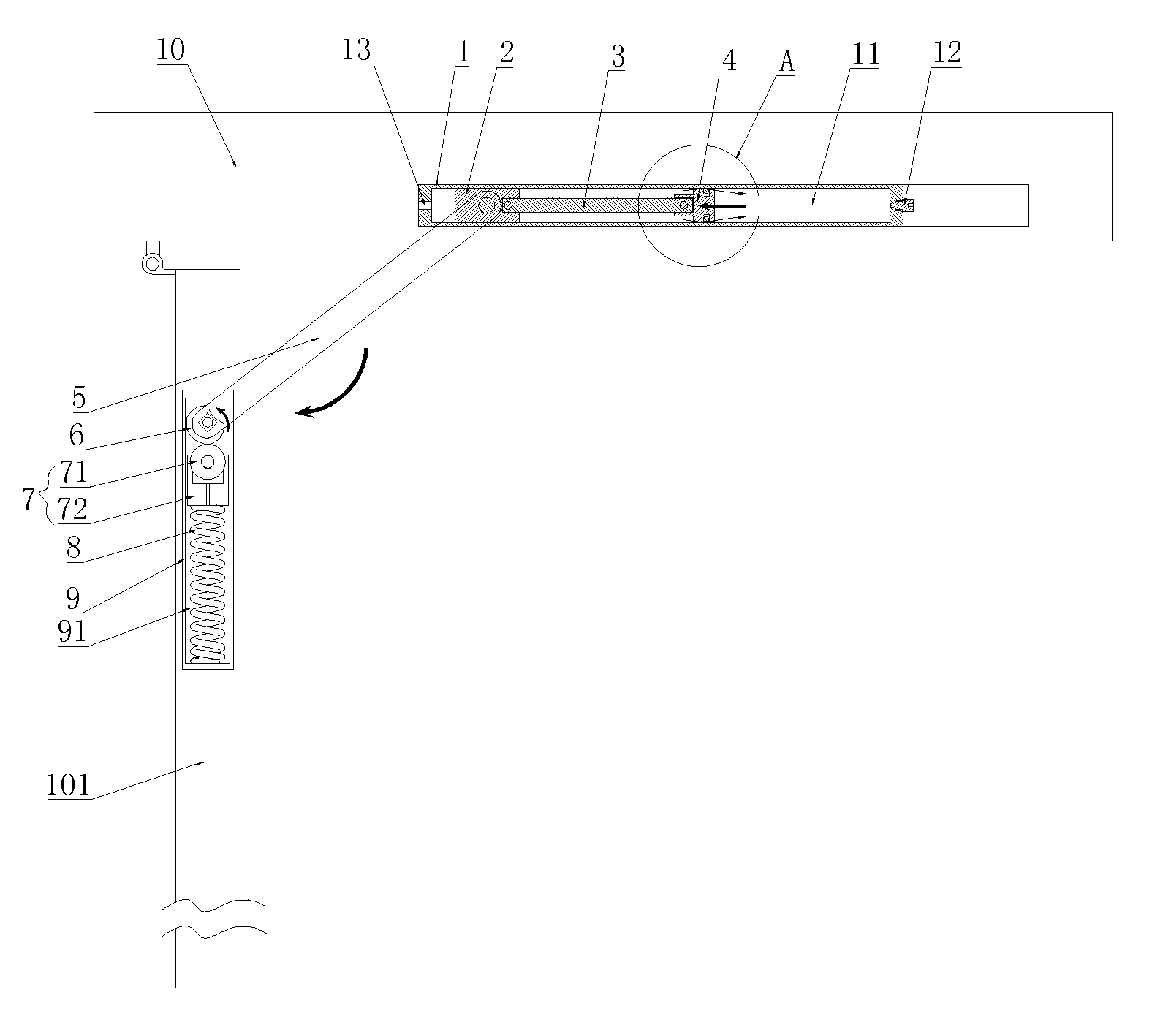
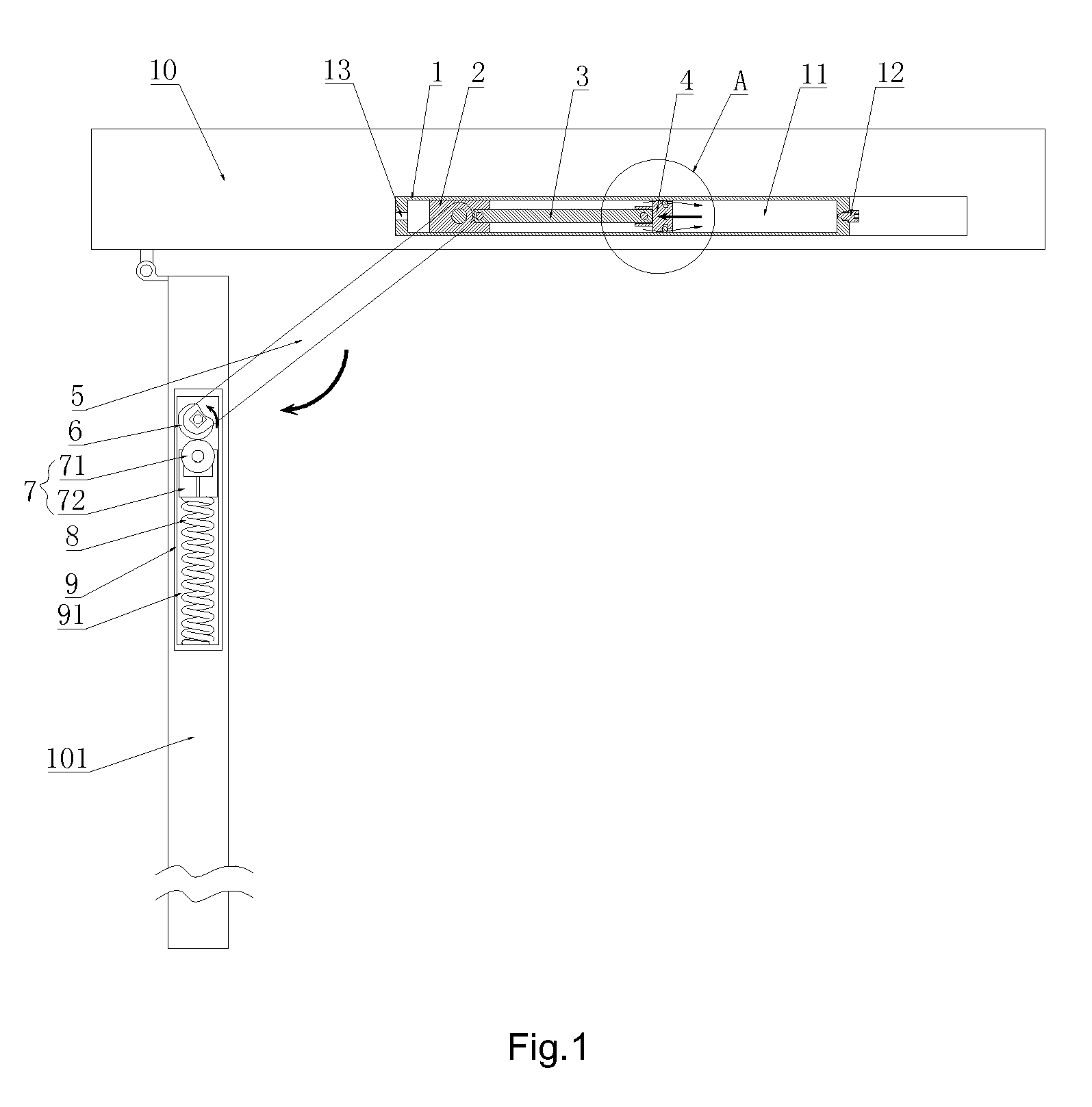
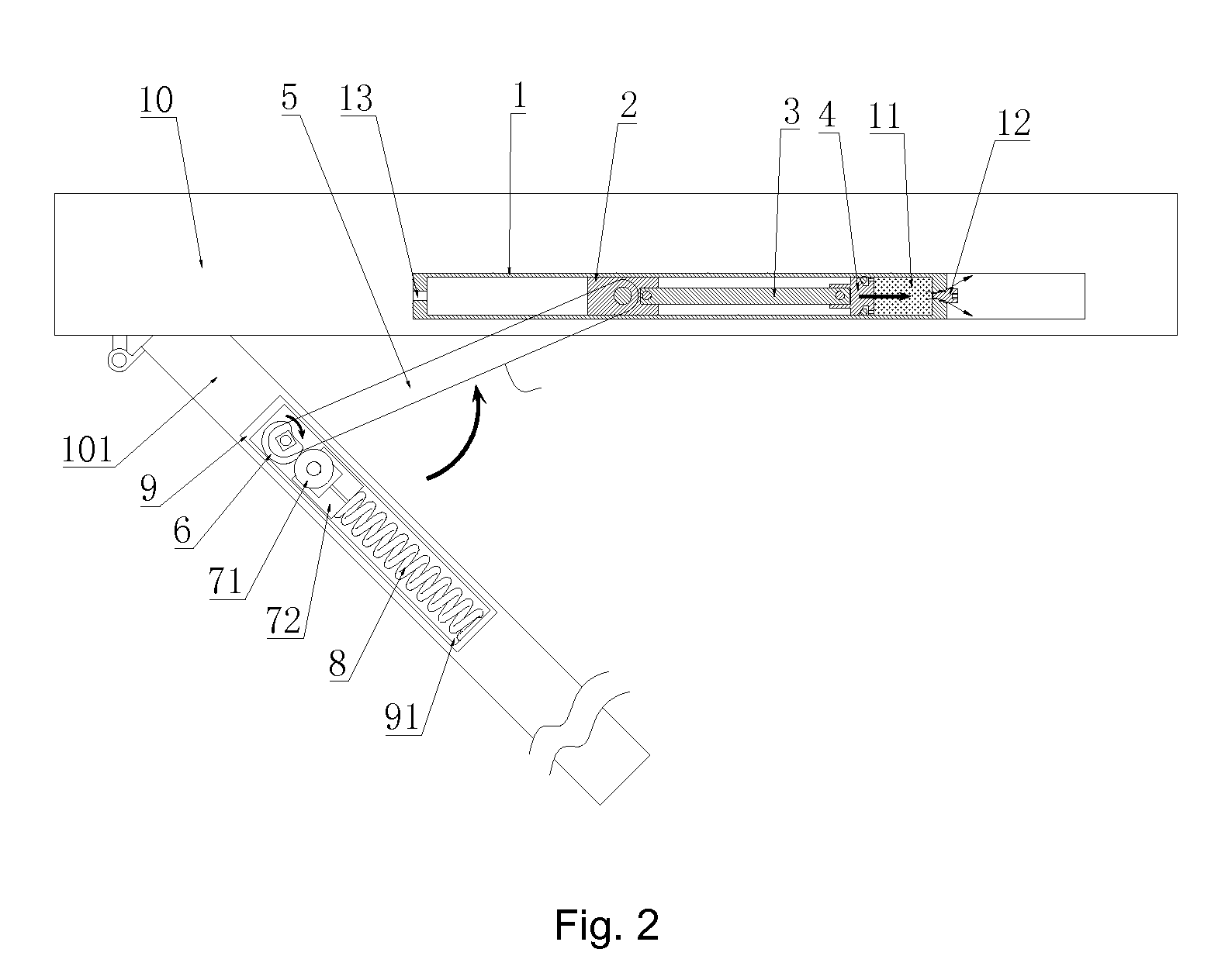
[0058]As shown in FIGS. 1 to 5, a door closer capable of adjusting its closing speed according to embodiments of the present invention, comprises a cylinder 1 configured on the door frame 10, a gas adjusting apparatus inside the cylinder 1, a housing 9 configured on the door where a receiving chamber 91 is set up inside the housing 9, a driving apparatus configured in the receiving chamber 91, and a lever 5 connecting the gas adjusting apparatus and a driving apparatus.

[0059]The gas adjusting apparatus comprises a sliding block 2, a piston 4 and a joint rod 3 for connecting the sliding block 2 and the piston 4, inside the cylinder 1; a hermetic chamber 11 is formed by the piston 4 and the cylinder 1, a regulating valve 12, for adjusting the exhaust velocity of the hermetic chamber 11, is configured on a side wall of the hermetic chamber 11. The other end of the cylinder 1 which is away from the hermetic chamber 11, is provided with a vent 13.

[0060]The piston 4 has an air-in configur...

embodiment 2

[0068]As shown in FIG. 6, the structure and work principle in this embodiment are identical to those in Embodiment 1, except the driving components. Here a pulley is a gear 73 and the driving component is a rack 74 engaged with the gear 73; the other end of the rack 74 is connected to the spring 8. One end of the lever 5 is hinged to the sliding block 2 while other end is fixed to the shaft of the gear 73.

[0069]When the door is open, the lever 5 drives the gear 73 rotating, the rack 74 is forced towards the spring 8, thereby the spring 8 possesses a great resilience. When the door 101 is released, the spring 8 drives the rack 74, and further the gear 73 rotating, such that the lever 5 drives the sliding block 2 sliding towards right side in FIG. 6, whereby the door can close automatically. The counteraction to the piston 4 could be adjusted by adjusting the exhaust of the regulating valve 12, and thereby the closing speed of the door can be adjusted.

[0070]In embodiments of the prese...


PUM


Abstract

A door closer capable of adjusting its closing speed, including a gas adjusting apparatus arranged on the door frame, a driving apparatus arranged on the door, and a lever is provided. One end of the lever is movably connected to the gas adjusting apparatus, and the other end is connected to the driving apparatus. The gas adjusting apparatus includes a sliding rail arranged on the door frame, and a sliding member cooperated with the sliding rail; a hermetic chamber is formed by the sliding member and the sliding rail, an adjusting member, for adjusting the exhaust of the hermetic chamber, is configured on a side wall of the hermetic chamber. The lever is movably configured on the sliding member.

Description

CROSS REFERENCE TO RELATED APPLICATION[0001]This application claims priority to Chinese Application No. CN 201510318849.8 having a filing date of Jun. 11, 2015, the entire contents of which are hereby incorporated by reference.FIELD OF TECHNOLOGY[0002]The following relates to the field of door closers, in particular a door closer capable of adjusting its closing speed.BACKGROUND[0003]The closing speed of a door closer is usually controlled by controlling the flow velocity of oil therein. However, the viscosity of oil varies upon changing temperature, to affect the closing speed of door closers greatly in the regions having big diurnal temperature amplitude, e.g. North America and the North China. It can be known from the experiments, the closing time of a hydraulic door closer is about 8 seconds at 25° C., but when the air temperature dropped down to minus 20° C., the closing time is increased to about 2 minutes, which is 15 times the former. A much longer closing time can cause man...

Claims


Application Information

Patent Timeline
Patent Type & Authority Patents(United States)
IPC IPC(8): E05F1/10E05F3/00E05F3/02E05F5/08
CPCE05F3/02E05F5/08E05F3/10E05F3/104E05F2003/228E05Y2201/686E05Y2900/132
Inventor FAN, SHUIWANG
Owner CMECH (GUANGZHOU) INDUSTRIAL LTD
Why Eureka
Try Eureka