Waterjet propulsion system and watercraft having a waterjet propulsion system

a technology of waterjet propulsion system and watercraft, which is applied in the direction of waterborne vessels, vessel construction, and propellant elements, can solve the problems of high acquisition and maintenance costs, and the need for seal bushings, and achieve the effect of low drive power

Active Publication Date: 2020-06-23
DESCH ANDREAS
View PDF15 Cites 0 Cited by
  • Summary
  • Abstract
  • Description
  • Claims
  • Application Information

AI Technical Summary

Benefits of technology

[0008]It is therefore the object of the invention to provide a waterjet propulsion system of the type mentioned, in which the mentioned disadvantages can be

Problems solved by technology

Such known waterjet propulsion systems have the disadvantage that due to the guidance of the drive shaft a sealed shaft bushing is required.
Such a shaft bushing is technically complex and maintenance-intensive.
This causes high acquisition and maintenance costs.
Such a shaft bushing also has a high friction, thus necessitating high drive power.
Furthermore, this drive shaft directly crosses a flow area and causes turbulence either in front of the impeller or in the outlet nozzle, further reducing the efficiency of such drives and, in turn, increasing the required drive power.
In addition, this can lead to cavitation on the drive shaft.
Furthermore, the drive shaft transmits rotational energy to the surrounding water, which leads to a deterioration of the flow conditions in the intake or nozzle area, and leads to a further braking of the drive shaft and an increase in the required drive power.
Known waterjet propulsion systems also have a h

Method used


Image

  • Waterjet propulsion system and watercraft having a waterjet propulsion system
  • Waterjet propulsion system and watercraft having a waterjet propulsion system
  • Waterjet propulsion system and watercraft having a waterjet propulsion system

Examples


Embodiment Construction

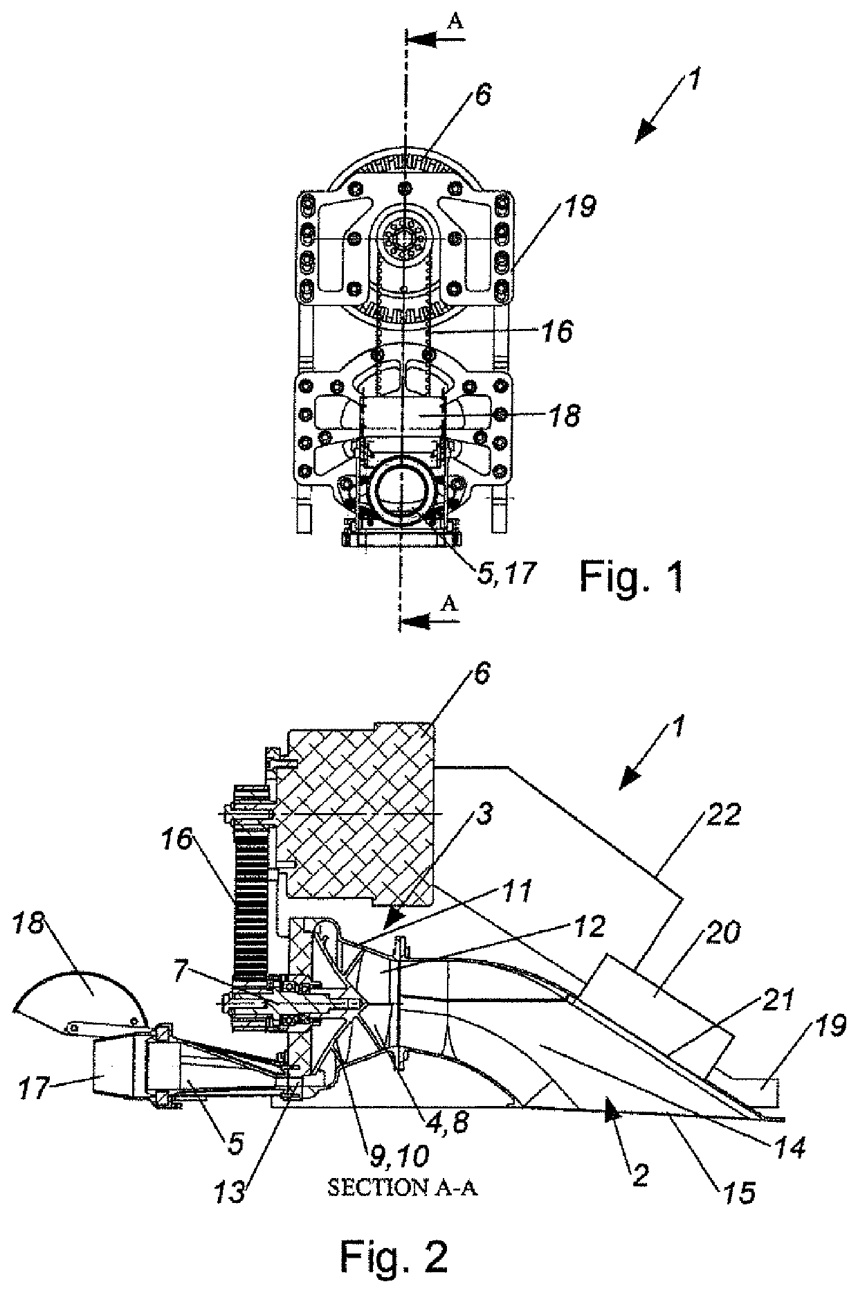
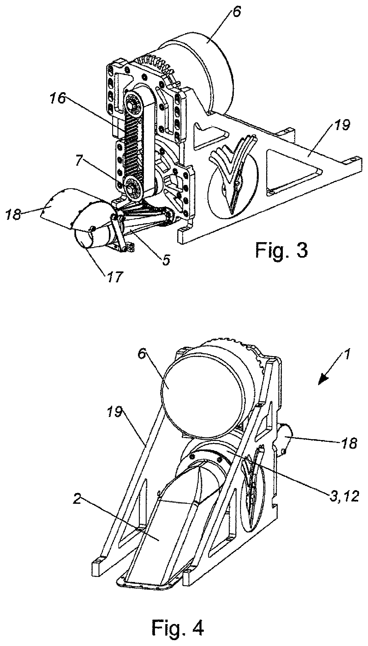
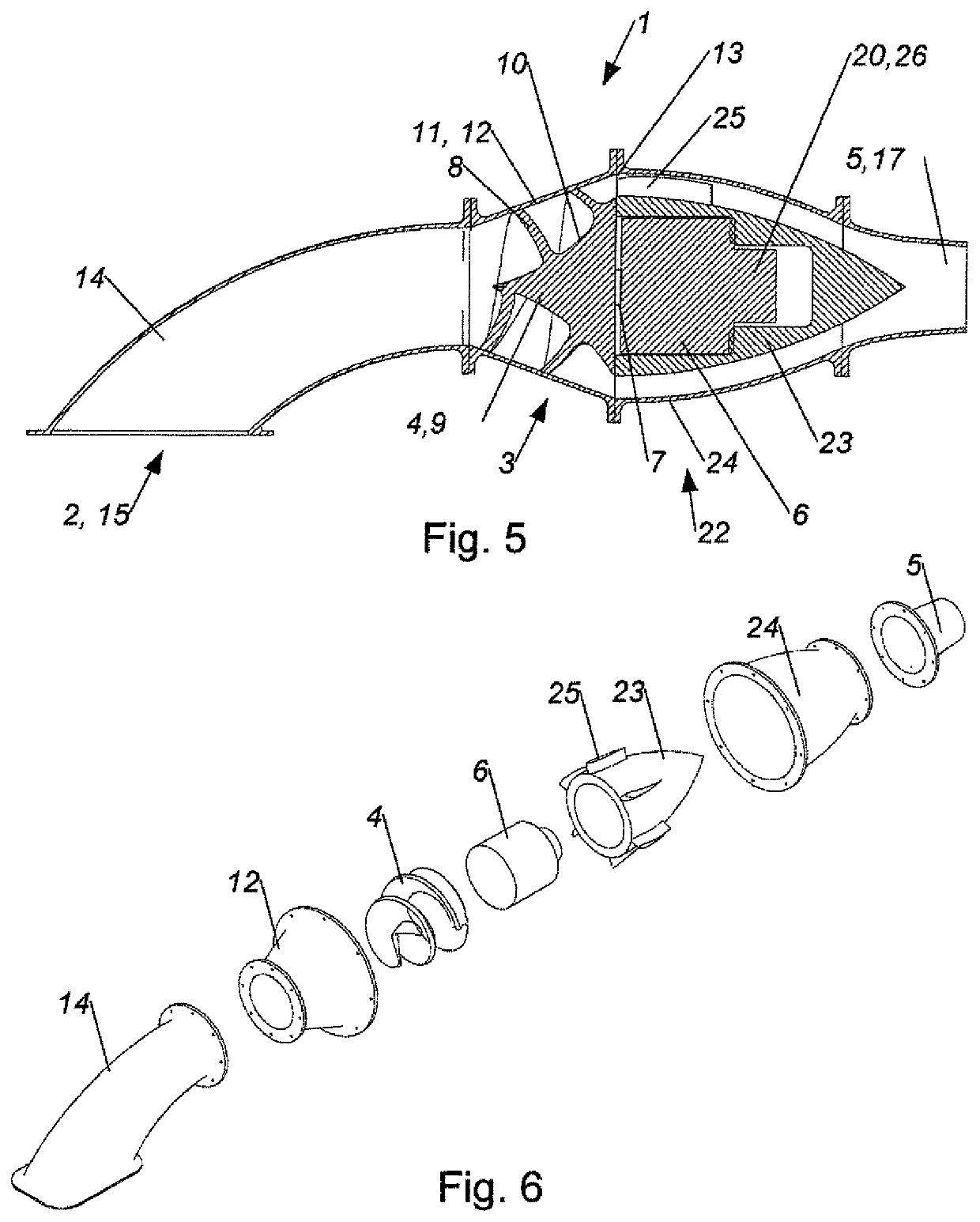
[0023]FIGS. 1 to 6 show different views of a preferred embodiment of a waterjet propulsion system 1 for a watercraft, having an intake region 2, an impeller region 3 adjoining the intake region 2, in which a single-stage impeller 4 is arranged, and one outlet nozzle 5 adjoining the impeller region 3, wherein the waterjet propulsion system 1 has a drive motor 6 which is at least indirectly connected to an impeller drive shaft 7 of the impeller 4, wherein the impeller 4 has only a single blade 8.

[0024]The subject waterjet propulsion system 1 has a simple and above all compact design. The waterjet propulsion system 1 has a hydrodynamically clean structure, whereby the required drive power is low.

[0025]As a result, a waterjet propulsion system 1 can be created which only requires a low drive power. Because of the low drive power required, emission-free operation is also possible with an electric motor and batteries, wherein the waterjet propulsion system 1 is still able to supply enough...


PUM


Abstract

The invention relates to a waterjet propulsion system (1) for a watercraft, comprising an intake region (2), an impeller region (3) which adjoins the intake region and in which a one-stage impeller (4) is mounted, and an outlet nozzle (5) which adjoins the impeller region, the waterjet propulsion system having a drive motor (6) which is at least indirectly connected to an impeller driveshaft (7) of the impeller (4). According to the invention, the impeller has only one single blade (8).

Description

CROSS-REFERENCES TO RELATED APPLICATIONS[0001]This application is the U.S. National Stage of International Application No. PCT / AT2016 / 000058, filed May 27, 2016, which designated the United States and has been published as International Publication No. WO 2016 / 187627 and which claims the priority of Austrian Patent Application, Serial No. A 333 / 2015, filed May 27, 2015, pursuant to 35 U.S.C. 119(a)-(d).BACKGROUND OF THE INVENTION[0002]The invention relates to a waterjet propulsion system.[0003]Waterjet propulsion systems are known which have an intake region, a compressor part and a drive nozzle. The compressor part in this case has a plurality of blades, which are driven by a drive shaft. The drive shaft is passed through the intake region or the drive nozzle.[0004]Such known waterjet propulsion systems have the disadvantage that due to the guidance of the drive shaft a sealed shaft bushing is required. Such a shaft bushing is technically complex and maintenance-intensive. This cau...

Claims


Application Information

Patent Timeline
IPC IPC(8): B63H11/08B63H11/103B63H21/17
CPCB63H11/08B63H11/103B63H21/17B63H2011/082F04D29/18F04D29/24F04D29/242
Inventor DESCH, ANDREASBAUMGARTNER, HUBERTWALDHERR, JOHANN
Owner DESCH ANDREAS
Why Eureka
Try Eureka