Combustion type power tool having buffer piece

a power tool and buffer piece technology, applied in the direction of manufacturing tools, stapling tools, nailing tools, etc., can solve the problems of reducing the entire efficiency of the power tool, lowering the driving power, and damaging the motor shaft and the cylinder head, so as to reduce the pressure of driving the piston, reduce the driving power, and reduce the effect of thermal vacuum

Active Publication Date: 2006-01-12
HITACHI KOKI CO LTD
View PDF12 Cites 14 Cited by
  • Summary
  • Abstract
  • Description
  • Claims
  • Application Information

AI Technical Summary

Benefits of technology

[0004] The present inventors have discovered the following drawbacks in the conventional combustion type power tool. First, the motor may also be laterally vibrated in a direction perpendicular to the sliding direction of the piston. The lateral vibration of the motor may allow the motor shaft to strike against the cylinder head to generate noise and to damage to the motor shaft and to the cylinder head. Second, a pressure leakage may occur through the gap between the motor shaft and the cylinder head at the time of explosion to reduce the pressure for driving the piston, to thus lower the driving power. Third, an effect of “thermal vacuum” is lowered since the gap is communicated with an atmosphere. Therefore, the movement of the piston toward its top dead center is lowered after the nail driving operation to lower the entire efficiency of the power tool.

Problems solved by technology

The lateral vibration of the motor may allow the motor shaft to strike against the cylinder head to generate noise and to damage to the motor shaft and to the cylinder head.
Second, a pressure leakage may occur through the gap between the motor shaft and the cylinder head at the time of explosion to reduce the pressure for driving the piston, to thus lower the driving power.
Therefore, the movement of the piston toward its top dead center is lowered after the nail driving operation to lower the entire efficiency of the power tool.

Method used


Image

  • Combustion type power tool having buffer piece
  • Combustion type power tool having buffer piece
  • Combustion type power tool having buffer piece

Examples


first embodiment

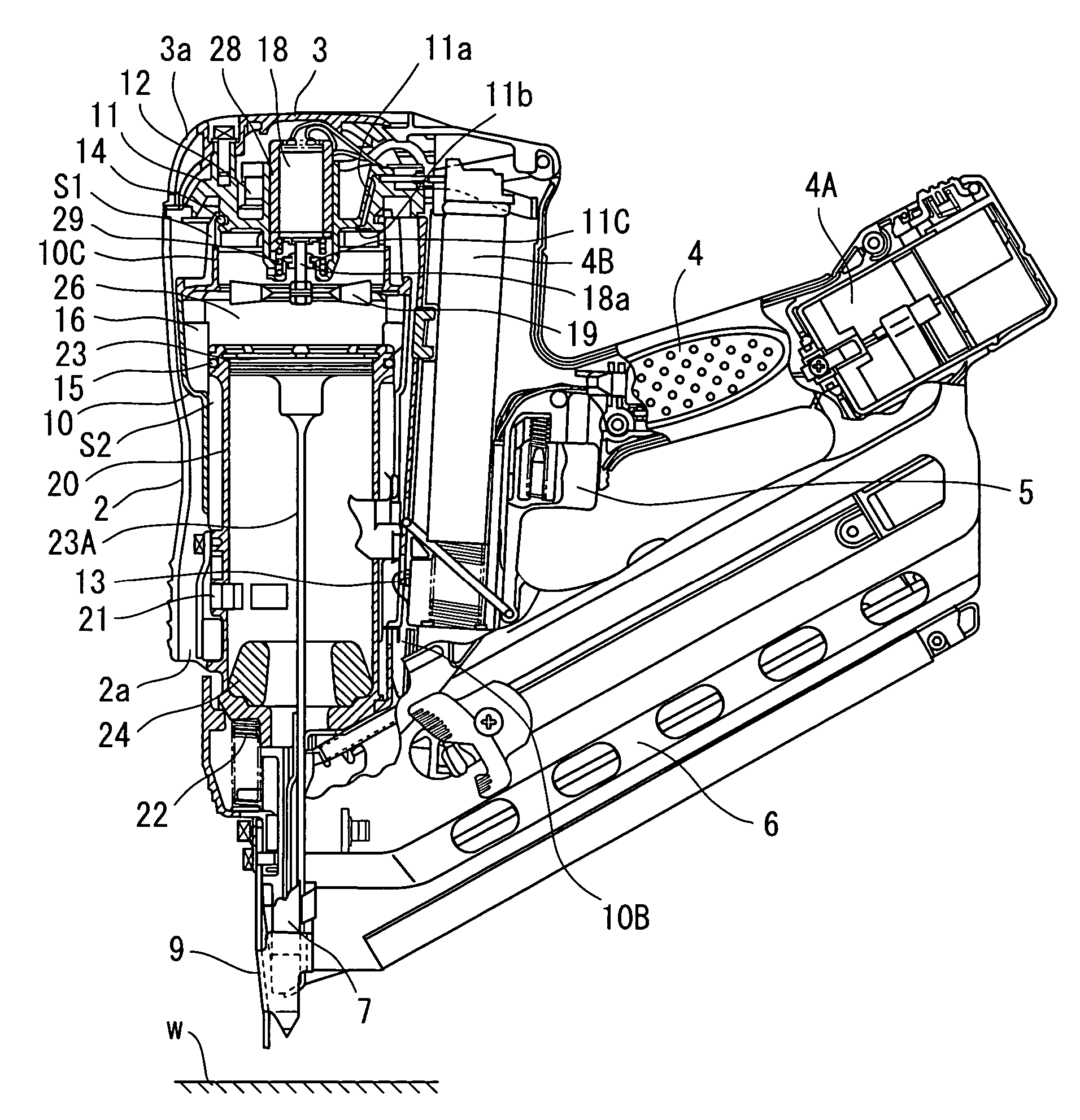
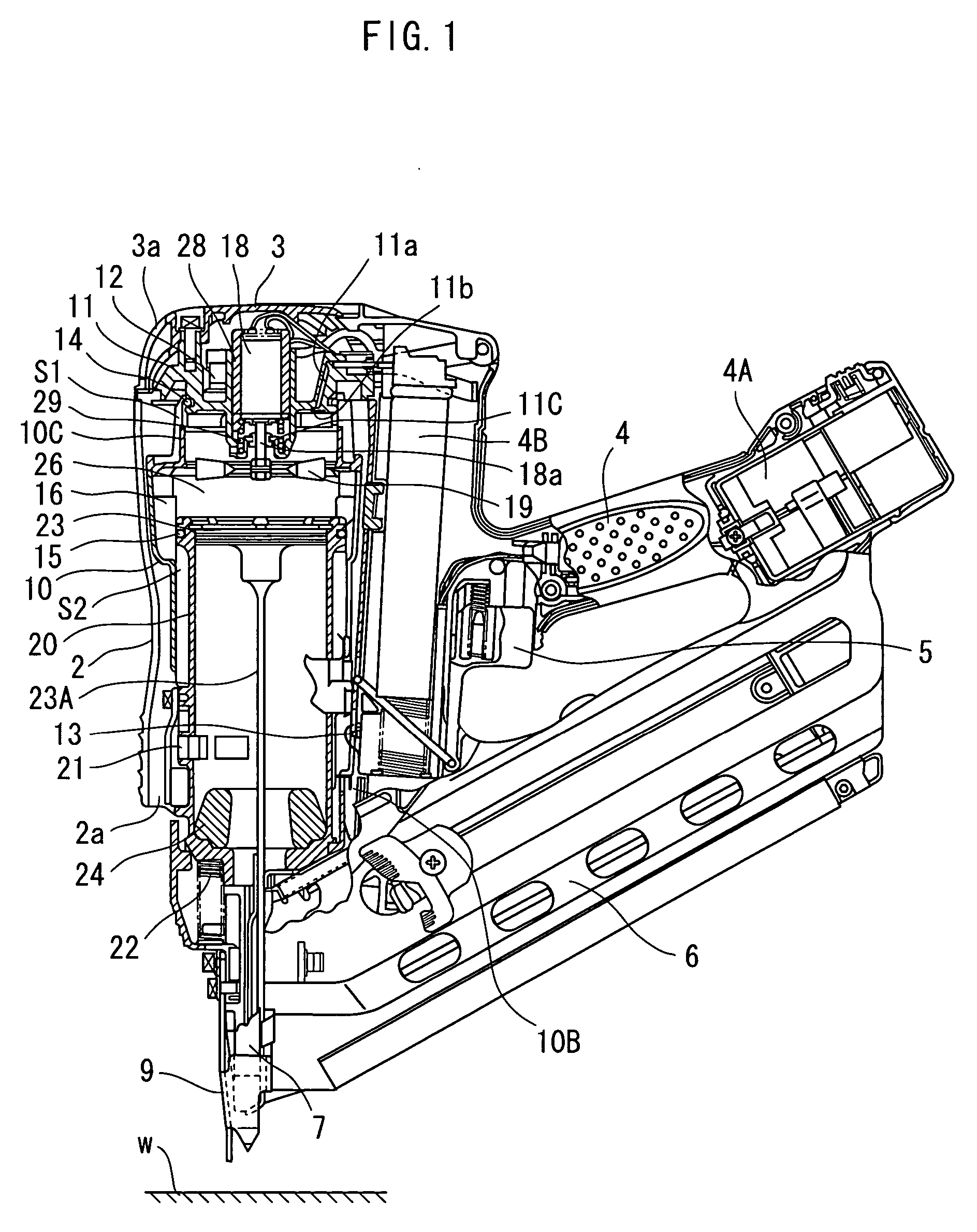
[0020] A combustion-type power tool according to the present invention will be described with reference to FIGS. 1 through 4. The embodiment pertains to a combustion type nail gun. The combustion type nail gun 1 has a housing 2 constituting an outer frame. A head cover 3 formed with an intake port 3a is mounted on the top of the housing 2. A handle 4 is attached to the housing 2 and extends from a side of the housing 2. The handle 4 has a trigger switch 5 and accommodates therein a battery 4A. A canister housing is provided in the handle 4 at a position immediately beside the housing 2. A gas canister 4B containing therein a combustible gas is detachably disposed in the canister housing. A magazine 6 is provided at a lower side of the handle 4. The magazine 6 contains nails (not shown). The housing 2 has a lower portion formed with an exhaust port 2a for discharging a combustion gas to the atmosphere.

[0021] A nose 7 extends from a lower end of the housing 2. The nose 7 is formed int...

third embodiment

[0048] A buffer piece 231 in a combustion type power tool is shown in FIG. 7. The buffer piece 231 has an annular protrusion 231D at second flange 231C. The annular protrusion 231D protrudes from an outer peripheral end portion of the second flange 231C toward the second contact surface 11e of the buffer support section 11C. The function and effect of the buffer piece 231 is the same as those of the buffer piece 131.

fourth embodiment

[0049] A buffer piece 331 in a combustion type power tool is shown in FIG. 8. A buffer piece has a sleeve portion 331A. The sleeve portion 331A does not have a circular cross-section, but has two parallel sides 331b, 331b and opposing arcuate sides 331c, 331c defining a diameter d3. A buffer support section 311C of a cylinder head is formed with a center hole 311c having a shape the same as and greater than a cross-sectional external contour of the sleeve portion 331A of the buffer piece so as to prevent the buffer piece from being freely rotated relative to the buffer support section 311C.

[0050] A combustion type power tool according to a fifth embodiment is shown in FIGS. 9 and 10. In the fifth embodiment, a second flange 431C of a buffer piece 431 made from a rubber is formed with an annular recess 431c, and a metal washer 432 made from aluminum or iron is fitted and held in the annular recess 431c. The washer 432 can be incorporated in the buffer piece 431 during molding.

[0051...


PUM


Abstract

A combustion type power tool having an arrangement avoiding direct striking of a drive shaft against a cylinder head when combustion pressure is exerted. A motor is disposed at the cylinder head and includes a motor body and a drive shaft extending in an axial direction and protruding into a combustion chamber. A fan is connected to the drive shaft to be rotatable within the combustion chamber. A buffer piece made from an elastic material is supported to the cylinder head. The buffer piece is movable relative to the cylinder head in a direction substantially perpendicular to the axial direction. The buffer piece is formed with a through-hole through which the drive shaft extends.

Description

BACKGROUND OF THE INVENTION [0001] The present invention relates to a combustion-type power tool, and more particularly, to such power tool capable of driving a fastener such as a nail, an anchor, and a staple into a workpiece. [0002] A combustion type power tool provides high operability in comparison with a pneumatically operated power tool requiring a compressor and a hose. In a conventional combustion-type driving tool such as a nail gun, a gaseous fuel injected into a combustion chamber is ignited to cause gas expansion in the combustion chamber, which in turn causes a linear momentum of a piston. By the movement of the piston, a nail is driven into a workpiece. In order to improve combustion, a motor having a motor shaft is supported to a cylinder head, and a fan connected to the motor shaft is disposed in the combustion chamber for agitating a combustible gas. Further, a bumper is disposed to absorb kinetic energy of the piston moving toward the workpiece. Such conventional c...

Claims


Application Information

Patent Timeline
Patent Type & Authority Applications(United States)
IPC IPC(8): B25C1/12F02B71/00
CPCB25C1/123B25C1/08F02B63/02F02B71/04
Inventor AKIBA, YOSHITAKAFUJISAWA, HARUHISANISHIKAWA, TOMOMASA
Owner HITACHI KOKI CO LTD
Why Eureka
Try Eureka