

Acoustic Turbine
a technology of acoustic turbine and acoustic shaft, which is applied in the direction of fluid couplings, rotary clutches, couplings, etc., can solve problems such as plate movement, and achieve the effect of high efficiency
Active Publication Date: 2011-06-09
SONIC DYNAMICS
View PDF4 Cites 0 Cited by
- Summary
- Abstract
- Description
- Claims
- Application Information
AI Technical Summary
Benefits of technology
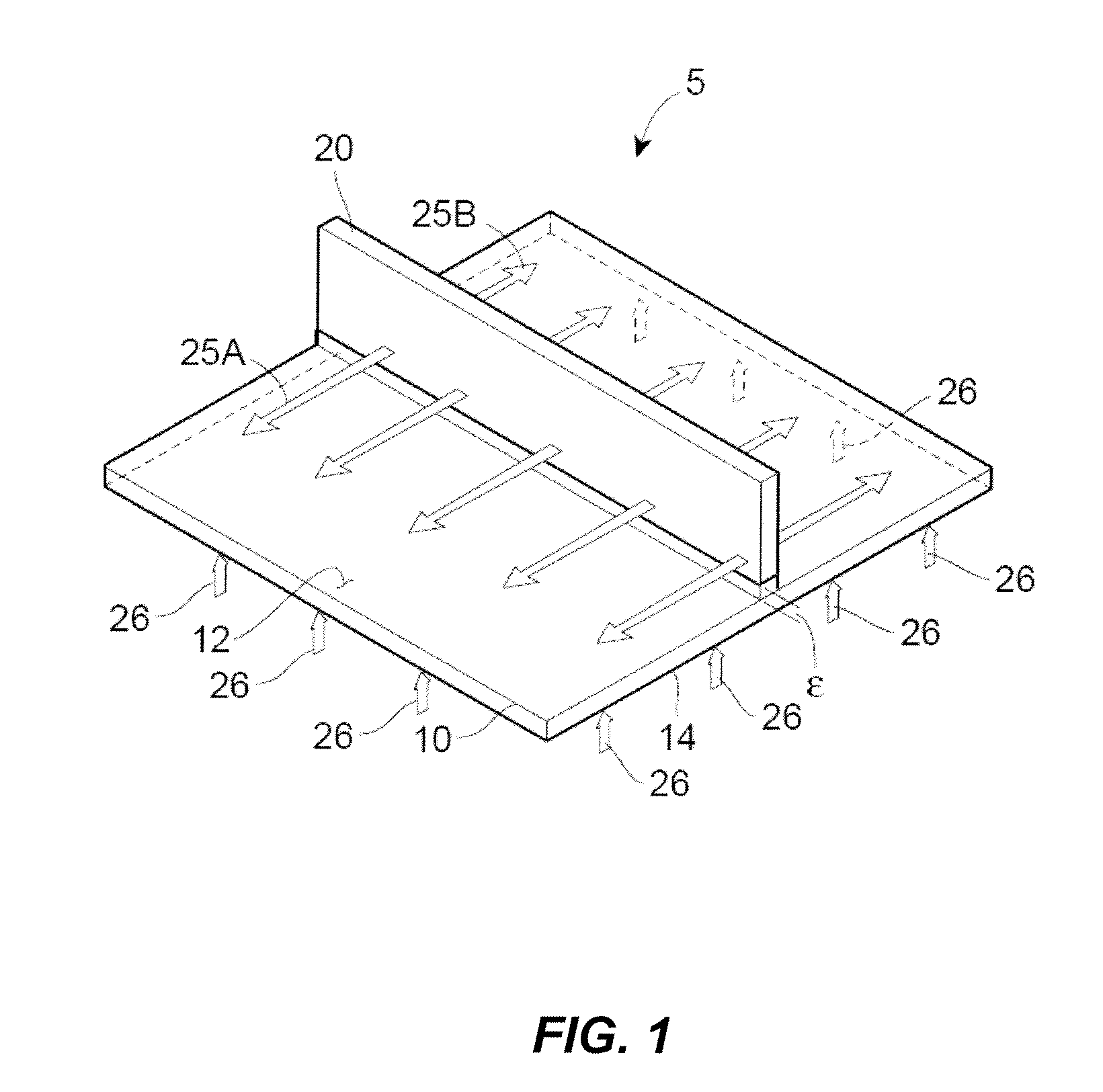
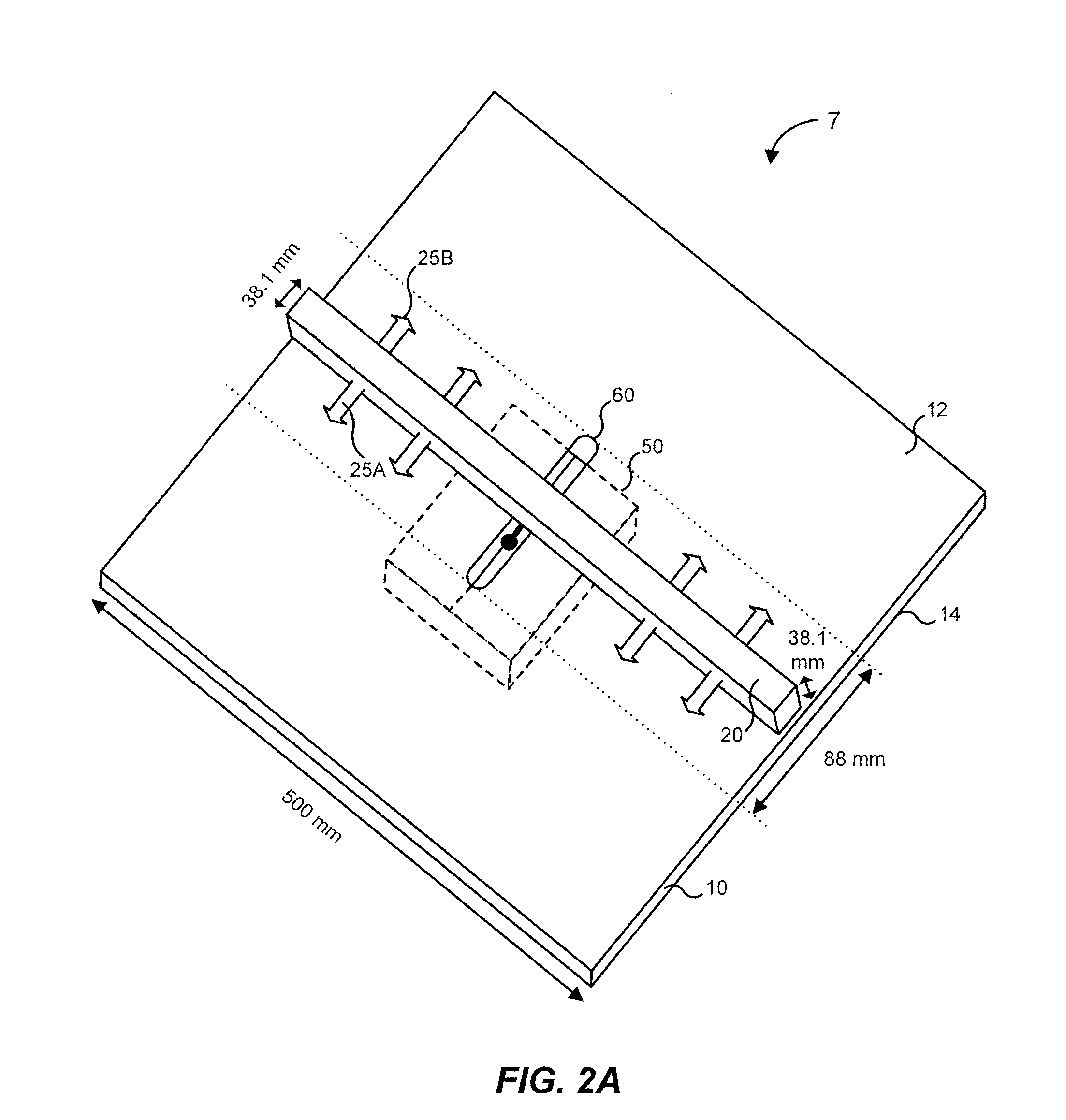
[0010]The operating principle of this system is analogous to the forces that result in lift on an airplane wing, in which faster air flow over the top of the wing, as compared to slower air flow over the bottom of the wing, causes a pressure difference on the opposite sides of the wing which, in turn, causes lift. Consistent with Bernoulli's law (which predicts the lift of an airplane wing), a sonic oscillator, properly configured, produces sound waves that result in a pressure drop on one side of the plate or other barrier element as compared to the opposite side of the plate or barrier element. This pressure difference results in enough thrust to turn a mechanical gear or other rotating mechanism. This system and method can therefore be used as part of a motor to produce rotation, or as part of a generator to generate electrical energy.
Problems solved by technology
The difference in fluid pressure on opposite sides of the plate results in net positive thrust on the plate, thereby causing movement of the plate.
Method used
View moreImage
Smart ImageViewing Examples

Examples
example 1
[0091]α=1000 cm
[0092]L=100 cm
[0093]S=100 cm
[0094]H=10 cm
[0095]#Rm=100
[0096]Ω=1 watt.
In this example, the constraints (C1′)-(C3′) become:
5.229×10⁴s>>f9.249×1011s2>>f2f>>1.870×10²s
and these constraints may be consistently satisfied for f=2×10³ hertz.
example 2
[0097]α=100 cm
[0098]L=20 cm
[0099]S=5 cm
[0100]H=1 cm
[0101]#Rm=100
[0102]Ω=0.25 watt.
In this example, the constraints (C1′)-(C3′) become:
2.253×10⁵s>>f9.249×1012s2>>f2f>>1.870×10³s
and these constraints may be consistently satisfied for f=2×10⁴ hertz.
example 3
[0103]α=5 cm
[0104]L=2.5 cm
[0105]S=2 cm
[0106]H=0.5 cm
[0107]#Rm=40
[0108]Ω=0.001 watt.
In this example, the constraints (C1′)-(C3′) become:
Login to View More PUM
 Abstract
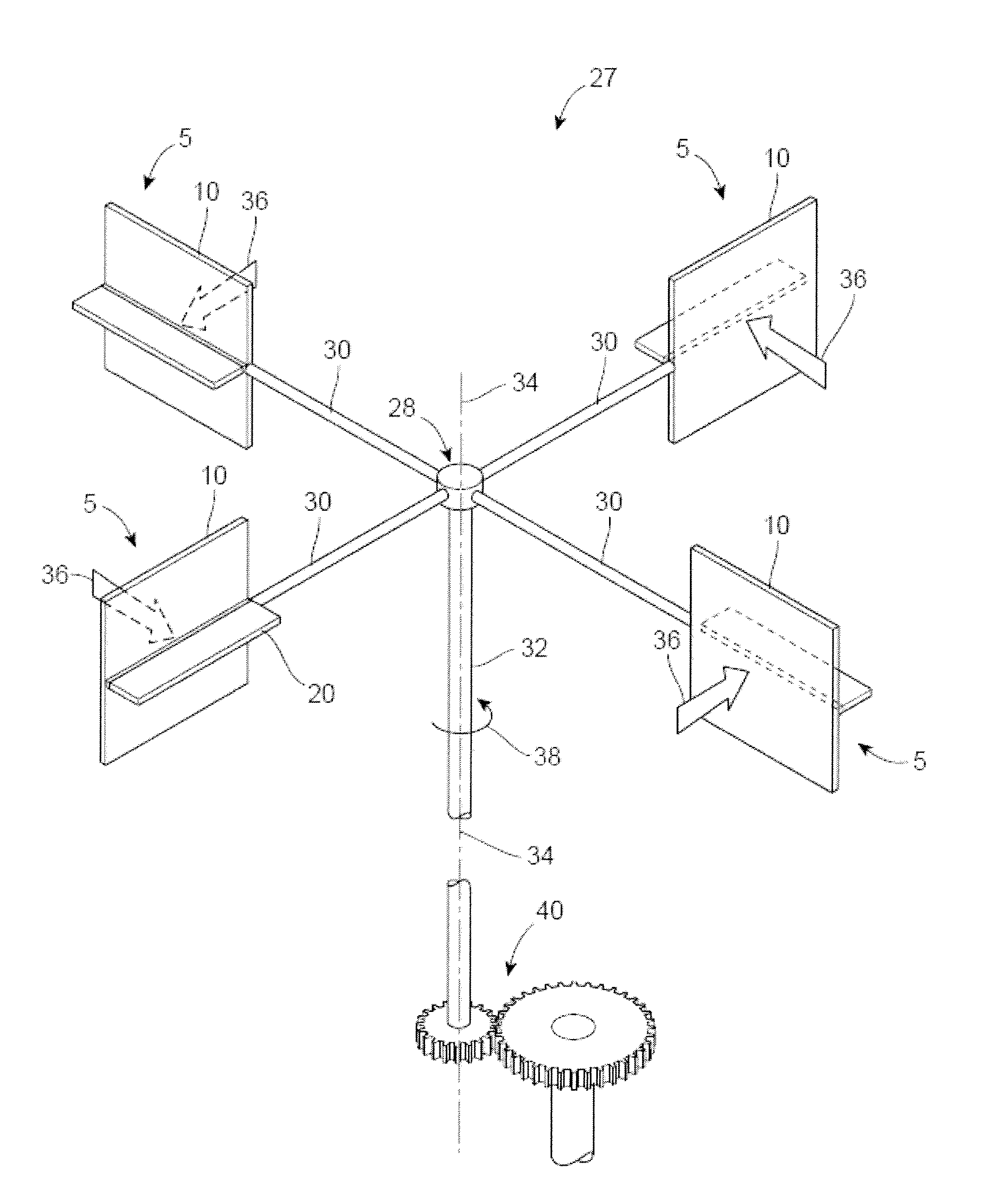
A method and apparatus generates kinetic and electrical energy using sound waves and is believed to be particularly useful in high efficiency motors and electrical generators. In particular, the method and apparatus uses sound waves as a catalyst to convert ambient heat energy into kinetic and / or electrical energy. In one embodiment, sound waves at particular frequencies are propagated across one side of a plate or other barrier element, causing flow of fluid (e.g. air) across the surface of the plate which, in turn, causes a reduction in the ambient fluid (air) pressure near the surface of the plate. The difference in fluid pressure on opposite sides of the plate results in net positive thrust on the plate, thereby causing movement of the plate. This movement can be harnessed using, for example, a windmill type of rotor and stator arrangement to generate useful kinetic and electrical energy.
Description
CROSS-REFERENCE TO RELATED APPLICATION[0001]This application claims priority to and the benefit of the filing date of U.S. Provisional Patent Application No. 61 / 028,974, entitled “Acoustic Production of Kinetic and Electrical Energy,” which was filed on Feb. 15, 2008, the entire disclosure of which is hereby incorporated by reference herein.TECHNICAL FIELD[0002]This application is generally related to the conversion of energy into useful work, and more specifically is related to a method and apparatus for converting heat energy into useful kinetic and electrical energy using acoustic energy.BACKGROUND OF THE RELATED ART[0003]Sound fields have been used to levitate objects by taking advantage of the Boltzmann-Ehrenfest principle of adiabatic invariance, which relates the acoustic potential acting on an object positioned in a single-mode cavity to a shift in resonant frequency caused by the presence of the object. In Putterman et al., “Acoustic Levitation and the Boltzmann-Ehrenfest P...
Claims
Login to View More Application Information
Patent Timeline
 IPC IPC(8): F15B21/12
CPCB08B7/02F03G7/002H02N11/006H02K7/1823F03H99/00
InventorTHURBER, JAMES K.THURBER, JONATHAN K.
OwnerSONIC DYNAMICS