Projection zoom lens and projection type display device

a projection zoom and display device technology, applied in the field of projection zoom lenses, can solve the problems of likely fluctuation of field curvature caused by magnification change, and achieve the effect of wide utilizable range, high zoom ratio, and favorable correction of field curvature fluctuations

Active Publication Date: 2017-01-31
FUJIFILM CORP
View PDF30 Cites 2 Cited by
  • Summary
  • Abstract
  • Description
  • Claims
  • Application Information

AI Technical Summary

Benefits of technology

[0051]The above advantageous effects will be exhibited more prominently in the case that the projection zoom lens of the present invention satisfies Conditional Formulae (3) and (4). Particularly, it will become possible to favorably correct fluctuations in field curvature. The above advantageous effect will become even more prominent in the case that the conditional formula below is satisfied within the range defined by Conditional Formula (4).
[0052]In addition, a high zoom ratio can be secured and the utilizable range of the projection zoom lens can be broadened, if the projection zoom lens of the present invention satisfies aforementioned Conditional Formula (5).1.4<Zr  (5)
[0053]The above advantageous effects will become more prominent in the case that the conditional formula below is satisfied within the range defined by Conditional Formula (5).1.6<Zr  (5′)
[0054]In addition, the following advantageous effects can be obtained in the case that the projection zoom lens of the present invention satisfies aforementioned Conditional Formula (6).−2.0<f1 / fw<−0.8  (6)
[0055]That is, if the value of f1 / fw is less than or equal to −2.0, the outer diameters of the lenses toward the magnification side will increase, which will lead to the zoom lens becoming large, and it will also become difficult to secure a sufficient amount of back focus. However, such problems can be avoided if the value of f1 / fw is greater than −2.0. That is, the outer diameters of the lenses toward the magnification side can be decreased to enable the zoom lens to be formed compact, and a sufficient amount of back focus can be secured if the value of f1 / fw is greater than −2.0.
[0056]In addition, if the value of f1 / fw is greater than or equal to −0.8, correction of field curvature and distortion will become difficult. However, this problem can be avoided if the value of f1 / fw is less than −0.8. That is, field curvature and distortion can be favorably corrected if the value of f1 / fw is less than −0.8.

Problems solved by technology

However, fluctuations in distortion and field curvature caused by changes in magnification are likely to occur if conventional projection zoom lenses are configured to have a high zoom ratio.

Method used


Image

  • Projection zoom lens and projection type display device
  • Projection zoom lens and projection type display device
  • Projection zoom lens and projection type display device

Examples


example 1

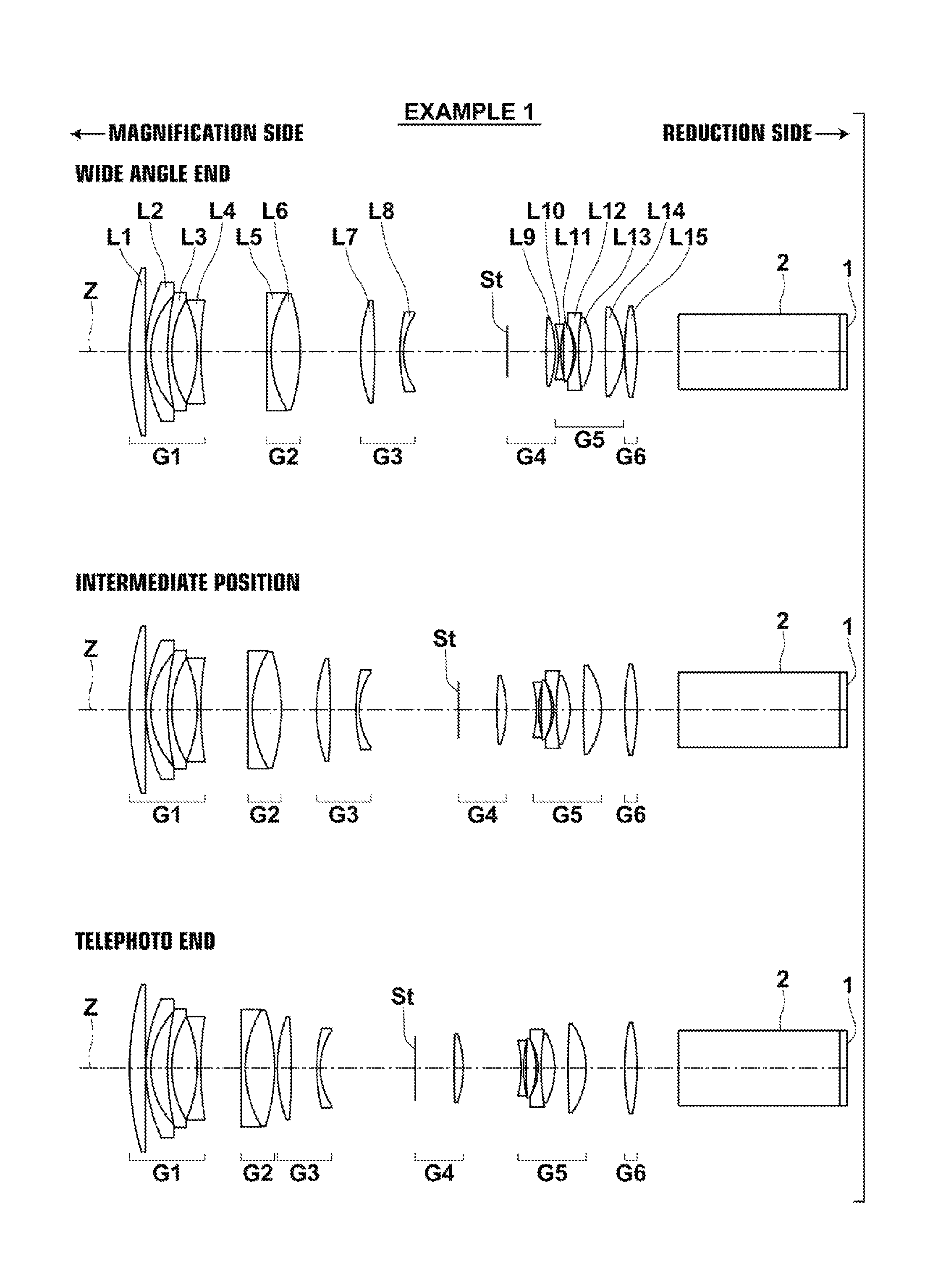
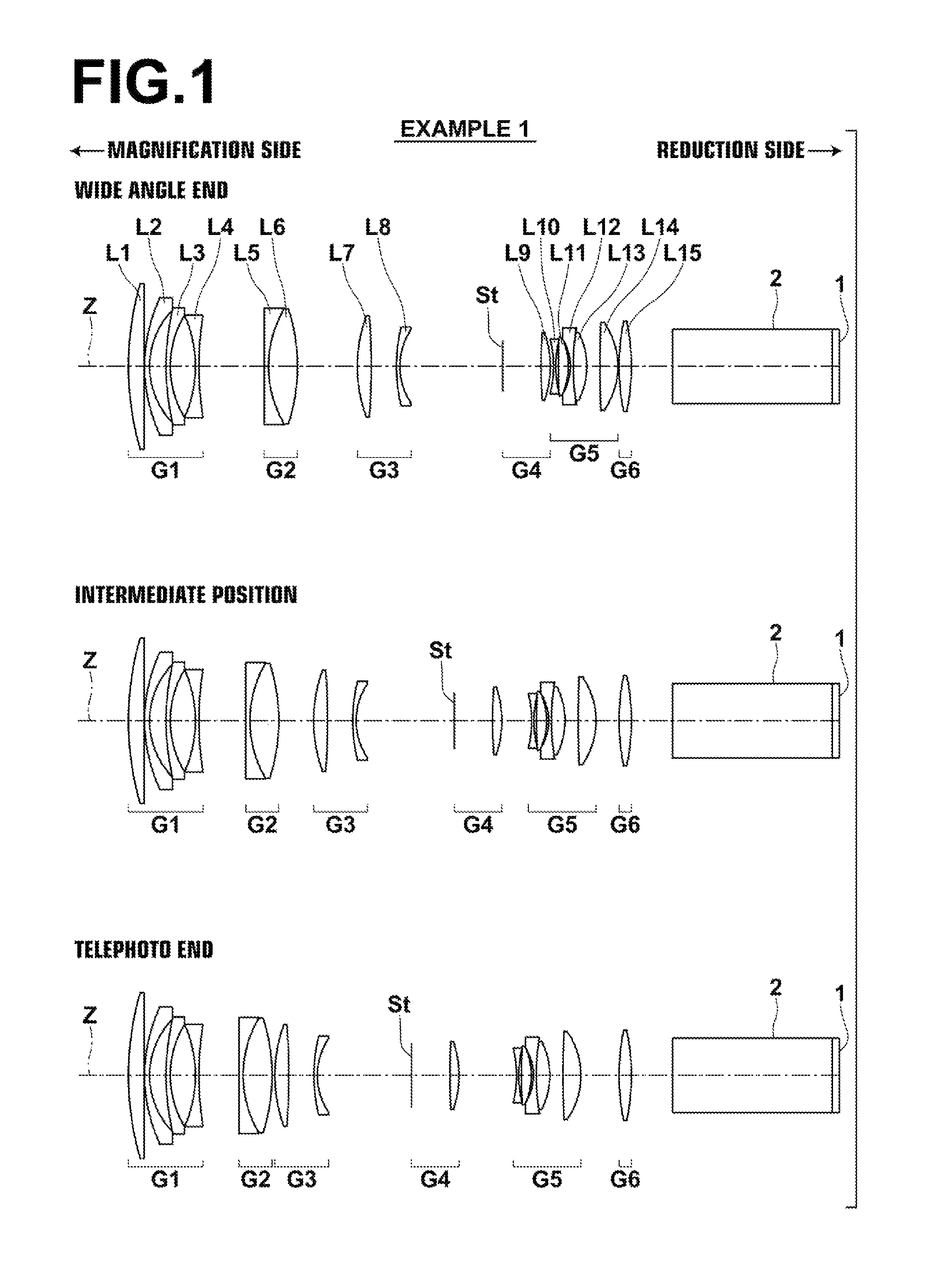
[0145]FIG. 1 illustrates the positions of lens groups of a projection zoom lens according to Example 1 of the present invention at a wide angle end, a telephoto end, and an intermediate position between the two. Because a description has already been given regarding FIG. 1, redundant descriptions will be omitted here.

[0146]In the projection zoom lens of Example 1, the first lens group G1 is constituted by four lenses, which are a first lens L1 having a positive refractive power (hereinafter, lenses will simply be referred to as “positive” or “negative”), a negative second lens L2, a negative third lens L3, and a negative fourth lens L4, provided in this order from the magnification side. The second lens group G2 is constituted by two lenses, which are a negative fifth lens L5 and a positive sixth lens L6, provided in this order from the magnification side.

[0147]The third lens group G3 is constituted by two lenses, which are a positive seventh lens L7 and a negative eighth lens L8, p...

example 2

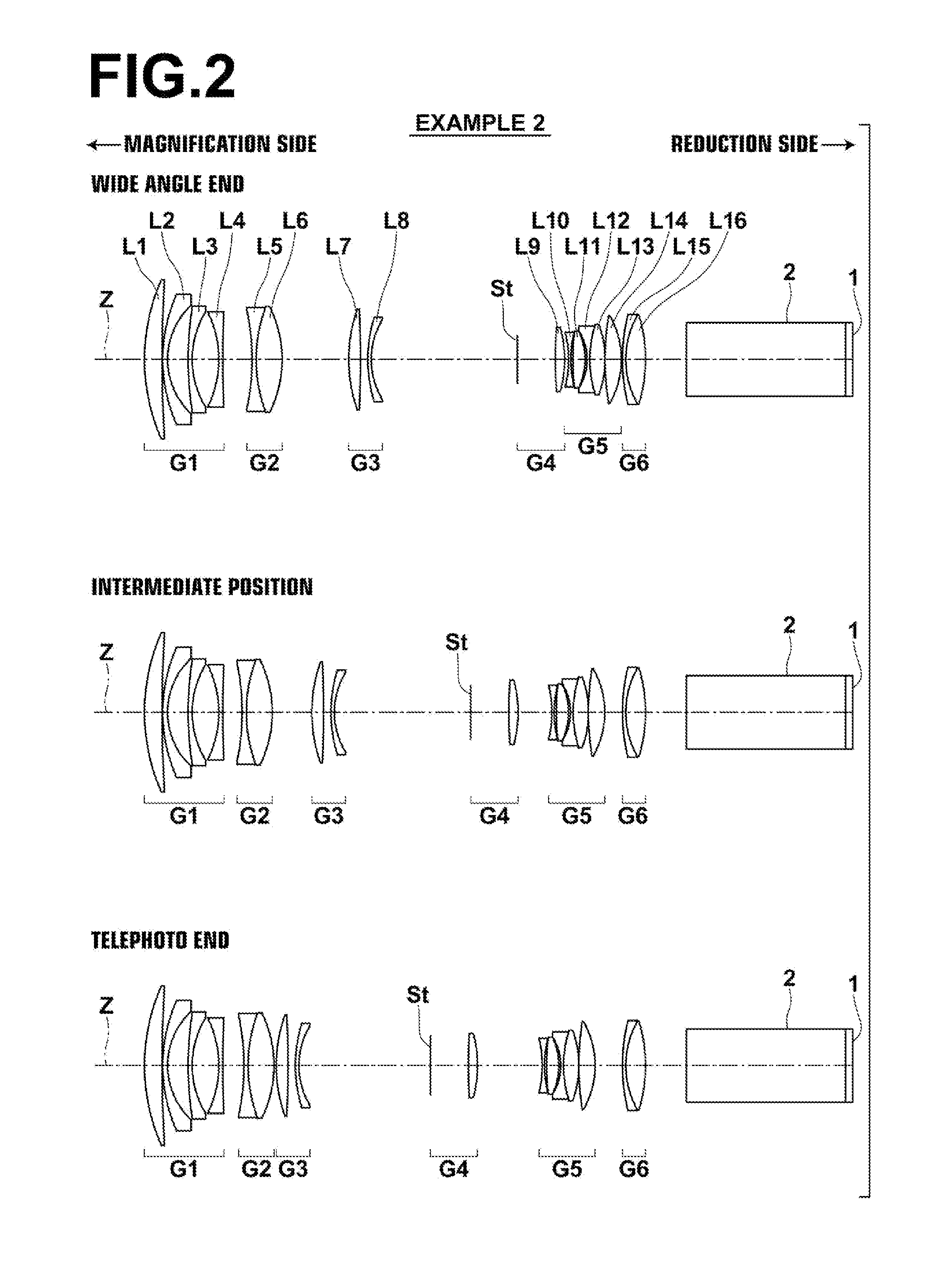
[0160]FIG. 2 illustrates the arrangements of lens groups of the projection zoom lens of Example 2 at the wide angle end, the telephoto end, and an intermediate position between the wide angle end and the telephoto end. In Example 2, a first lens group G1 is constituted by four lenses, which are a positive first lens L1, a negative second lens L2, a negative third lens L3, and a negative fourth lens L4, provided in this order from the magnification side. A second lens group G2 is constituted by a negative fifth lens L5 and a positive sixth lens L6, provided in this order from the magnification side.

[0161]A third lens group G3 is constituted by two lenses, which are a positive seventh lens L7 and a negative eighth lens L8, provided in this order from the magnification side. A fourth lens group G4 is constituted by and an aperture stop St, which is a variable stop, and a positive ninth lens L9 provided in this order from the magnification side.

[0162]A fifth lens group G5 is constituted...

example 3

[0168]FIG. 3 illustrates the arrangements of lens groups of the projection zoom lens of Example 3 at the wide angle end, the telephoto end, and an intermediate position between the wide angle end and the telephoto end. In Example 3, a first lens group G1 is constituted by four lenses, which are a positive first lens L1, a negative second lens L2, a negative third lens L3, and a negative fourth lens L4, provided in this order from the magnification side. A second lens group G2 is constituted by a negative fifth lens L5 and a positive sixth lens, provided in this order from the magnification side.

[0169]A third lens group G3 is constituted by two lenses, which are a positive seventh lens L7 and a negative eighth lens L8, provided in this order from the magnification side. A fourth lens group G4 is constituted by an aperture stop St, which is a variable stop, and a positive ninth lens L9, provided in this order from the magnification side.

[0170]A fifth lens group G5 is constituted by fi...


PUM


Abstract

A projection zoom lens constituted by: a negative first lens group; a positive final lens group; and moving lens groups between the first and the final lens groups that move independently while changing magnification, satisfies the conditional formulae below:1.00<(Rf2−Rr2) / (Rf2+Rr2)  (1)0.00≦(Rr2−Rf3) / (Rr2+Rf3)<0.15  (2)2.5<Bf / Imφ  (9)wherein Rf2 and Rr2 respectively are the radii of curvature of the front and rear surfaces of the second lens from the magnification side within the most reduction side moving lens group, Rf3 is the radius of curvature of the front surface of the third lens from the magnification side within the most reduction side moving lens group, Bf is the back focus of the entire system at the reduction side at the wide angle end as an air converted length, and Imφ is the maximum effective image circle diameter at the reduction side.

Description

CROSS REFERENCE TO RELATED APPLICATIONS[0001]The present application is a Continuation of PCT International Application No. PCT / JP2013 / 006614 filed on Nov. 11, 2013, which claims priority under 35 U.S.C. §119(a) to Japanese Patent Application No. 2012-253316 filed on Nov. 19, 2012. Each of the above applications is hereby expressly incorporated by reference in its entirety, into the present application.BACKGROUND OF THE INVENTION[0002]Technical Field[0003]The present invention is related to a projection zoom lens, and particularly to a projection zoom lens for use in a projection type display device.[0004]In addition, the present invention is related to a projection type display device equipped with a projection zoom lens.[0005]Background Art[0006]Conventionally, projection type display devices that utilize light valves, such as liquid crystal display elements, DMD's (Digital Micromirror Devices: registered trademark), etc., are in wide use. In addition, projection type display devi...

Claims


Application Information

Patent Timeline
Patent Type & Authority Patents(United States)
IPC IPC(8): G02B15/14G02B13/16G02B15/177G02B9/64G02B15/20G02B27/00G02B13/00G02B9/60G02B9/62G02B27/64G02B13/18G02B13/04G02B5/00
CPCG02B13/16G02B15/177G02B15/20G02B27/0025G02B5/005G02B9/60G02B9/62G02B9/64G02B13/002G02B13/009G02B13/0045G02B13/04G02B13/18G02B27/646G02B15/145531G02B15/1465
Inventor AMANO, MASARUNAGATOSHI, YUKIKOKAWANA, MASANAO
Owner FUJIFILM CORP
Why Eureka
Try Eureka