Ultrasound imaging apparatus

a technology of ultrasonic imaging and apparatus, applied in the field of ultrasonic imaging technique, can solve the problems of hampered enhancement of lateral resolution and constraints on lateral resolution, and achieve the effects of reducing computations, accurate estimation of point images, and more accurate point images

Inactive Publication Date: 2017-09-05
HITACHI LTD
View PDF17 Cites 1 Cited by
  • Summary
  • Abstract
  • Description
  • Claims
  • Application Information

AI Technical Summary

Benefits of technology

[0013]In the present invention, a process for computing the similarity is performed in advance as to the received signals, and an adaptive weight is computed by using thus obtained similarity, thereby reducing the amount of computations and achieving an accurate estimation of an point image. For example, by performing the process for computing the similarity in the time direction, it is possible to correct fluctuations in the time direction according to a relatively small amount of computations, and perform estimation of more accurate point image. With the configuration above, image blurring in the time direction (depth direction) is corrected, enabling acquisition of the point image being small in diameter, and allowing acquisition of an ultrasound image including little false images and noise in stable manner.

Problems solved by technology

On the other hand, as a basic problem of the ultrasound imaging apparatus, it is known that lateral resolution is subject to constraints.
In actual, however, a physical restriction in designing the apparatus, i.e., the length of the array, has hampered the enhancement of the lateral resolution.
Accordingly, there is a possibility that this brings a marked improvement in the lateral resolution, being one of essential problems in the beamforming technique.

Method used


Image

  • Ultrasound imaging apparatus
  • Ultrasound imaging apparatus
  • Ultrasound imaging apparatus

Examples


first embodiment

[0043]The ultrasound imaging apparatus according to the first aspect of the present invention as described above will be specifically explained as the first embodiment.

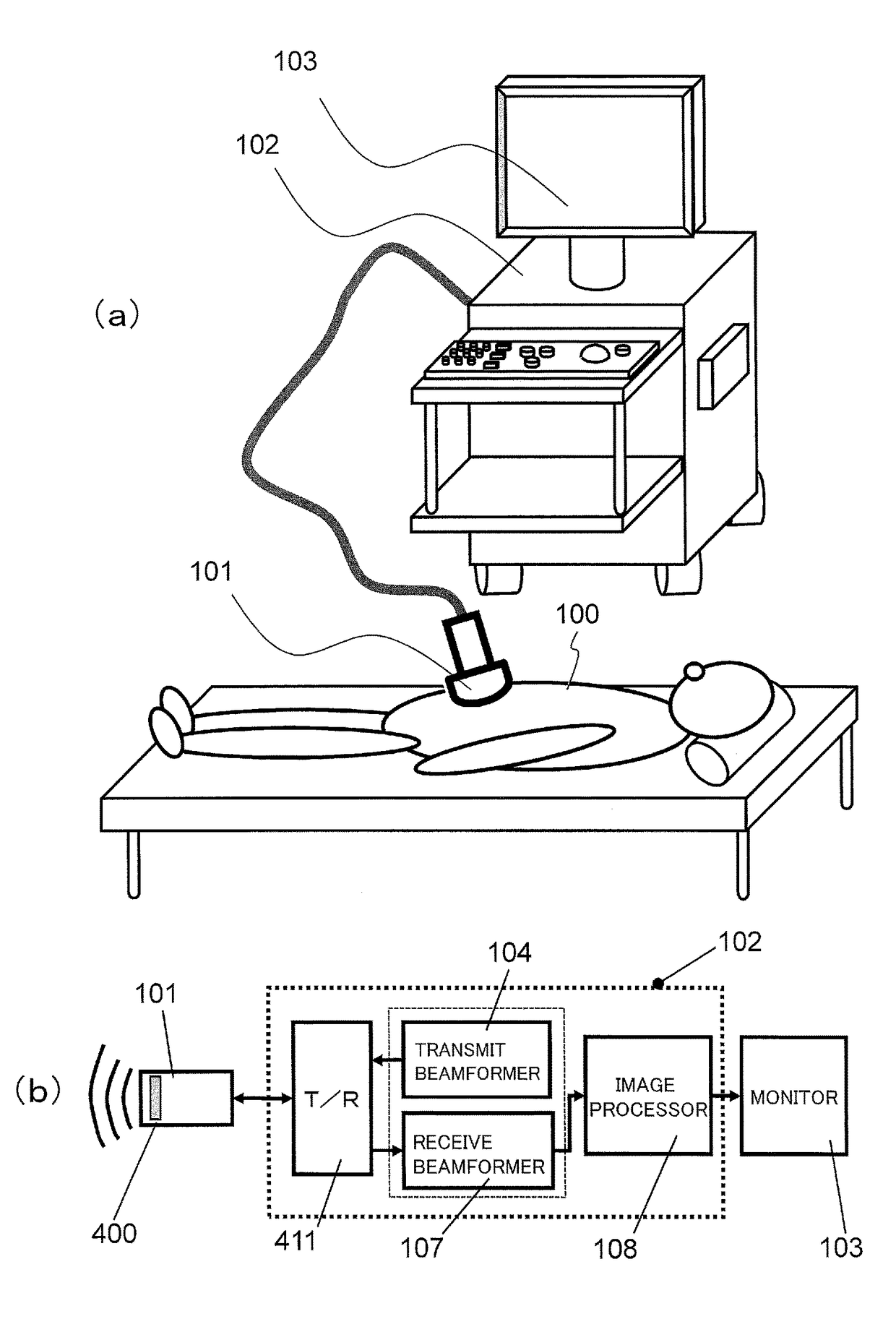
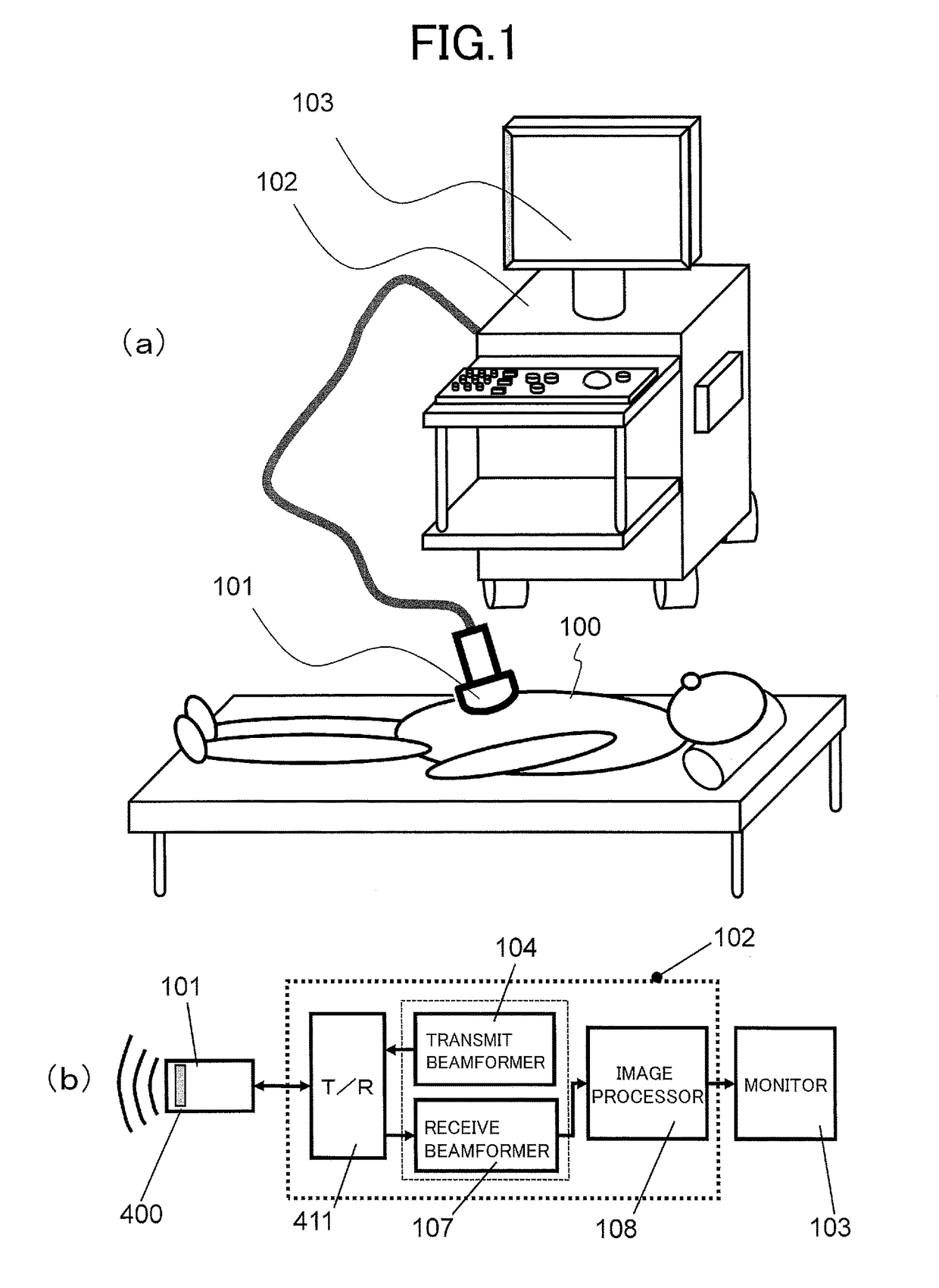
[0044]Firstly, with reference to FIG. 1(a) and FIG. 1(b), the entire configuration of the ultrasound imaging apparatus will be explained. FIG. 1(a) is a perspective view of the apparatus, and FIG. 1(b) is a block diagram illustrating a schematic configuration of the inside thereof.

[0045]As illustrated in FIG. 1(a), the ultrasound imaging apparatus is provided with the ultrasound probe 101, the apparatus main body 102, and the monitor 103. As illustrated in FIG. 1(b), there are arranged in the apparatus main body 102, the transmit beamformer 104, the transmit-receive separation circuit 411, the receive beamformer 107, and the image processor 108.

[0046]The transmit beamformer 104 generates signals of a transmission beam, allowing the signals to pass through the transmit-receive separation circuit 411, and thereafter tra...

second embodiment

[0086]With reference to FIG. 7, the ultrasound imaging apparatus according to the second embodiment of the present invention will be explained. FIG. 7 is a block diagram showing the receive beamformer 107 according the second embodiment. FIG. 8 is a flowchart illustrating the operations of each component in the receive beamformer 107.

[0087]In the second embodiment, the adaptive weight operator incorporates a weight memory for storing in advance multiple-type combinations of a distribution of the similarity and the weight value, and a weight estimator. The weight estimator selects a combination of the distribution of the similarity and the weight value being stored in the weight memory, based on multiple distributions of the similarity received from the similarity operator, thereby enabling a selection from the weight values associated with the multiple distributions of the similarity received from the similarity operator.

[0088]Specifically, as illustrated in FIG. 7, the receive beam...

third embodiment

[0096]The third embodiment is directed to a configuration where the adaptive weight operator has both the first operator and the second operator. The first operator uses the similarity obtained by the similarity operator to perform the adaptive signal processing, and computes the adaptive weight. The second operator is provided with the weight memory that stores in advance, multiple-type combinations of the distribution of similarity and the weight value, and the weight estimator. The weight estimator selects a combination of the distribution of the similarity and the weight value, being stored in the weight memory, thereby allowing a selection from the weight values associated with multiple distributions of the similarity received from the similarity operator. In addition, the adaptive weight operator may be provided with at least one of a drive switching part and an output switching part; the drive switching part is provided for selectively driving the first operator or the second...


PUM


Abstract

A weight value used for a beamforming process performed on received signals in an ultrasound imaging apparatus is obtained with a small amount of computations and with a high degree of precision, even when a method of adaptive signal processing is employed.Multiple elements 401 receive ultrasound signals from a test subject, and the similarity operator 404 obtains the similarity between the received signals x(n). By using the similarity C(n) between the received signals obtained by the similarity operator 404, the adaptive weight operator 407 computes the adaptive weight w(n) in association with the similarity. The beamforming operator 408 uses the adaptive weight w(n) and the received signal x(n) to generate a beamforming output. The imaging processor 108 uses the beamforming output to generate image data. By way of example, the similarity operator 404 performs computations of the similarity in the time direction.

Description

TECHNICAL FIELD[0001]The present invention relates to an ultrasound imaging technique for taking an image within a test subject, through the use of ultrasound wave.BACKGROUND ART[0002]Ultrasound imaging is a technique for non-invasively creating an image of the inside of a test subject including a human body, through the use of ultrasound wave (sound wave not intended for hearing, and generally high-frequency sound wave having 20 kHz or higher). By way of example, a medical ultrasound imaging apparatus will be briefly explained. An ultrasound probe transmits the ultrasound waves to the inside of a patient, and receives echo signals reflected from the inside of the patient.[0003]The received signals are subjected to signal processing in one or both of the ultrasound probe and the main unit of the ultrasound imaging apparatus, and thereafter transferred to a monitor and an ultrasound image is displayed thereon. More specifically, for example, a transmit beamformer in the main unit of ...

Claims


Application Information

Patent Timeline
Patent Type & Authority Patents(United States)
IPC IPC(8): H04N5/00G01S7/52A61B8/08G06K9/62G06T7/00G10K11/34H04N5/232A61B8/00G01S15/89
CPCG06K9/6202A61B8/5207G01S7/52047G01S15/8915G06T7/0012G10K11/346H04N5/232A61B8/4405A61B8/461A61B8/467G01S15/8927H04N23/632
Inventor IKEDA, TEIICHIROAZUMA, TAKASHIMASUZAWA, HIROSHI
Owner HITACHI LTD
Why Eureka
Try Eureka