Image recording apparatus

Inactive Publication Date: 2009-12-01
RICOH KK
View PDF16 Cites 1 Cited by
  • Summary
  • Abstract
  • Description
  • Claims
  • Application Information

AI Technical Summary

Benefits of technology

[0017]In addition, when arranging the detection unit near the photoconductor along the main scanning direction, for example, at a position before a starting scanning position, it is possible to correct the image dot intervals in the main scan direction on the scanning surface, enabling formation of images without fluctuation of image dot intervals in the main scan direction. Furthermore, when arranging the

Problems solved by technology

However, the laser diodes are usually inclined in different ways, and furthermore in different laser driving units, and even in the same laser diode array, the intervals between two laser diodes are not constant.

Method used


Image

  • Image recording apparatus
  • Image recording apparatus
  • Image recording apparatus

Examples


first embodiment

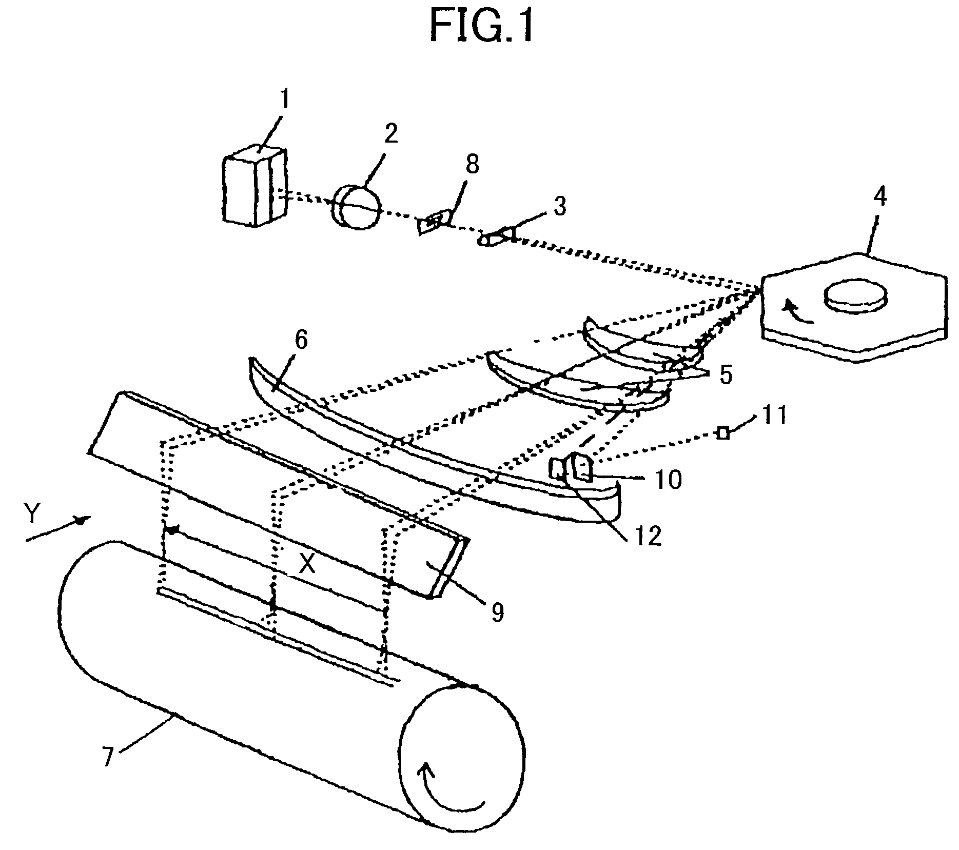
[0034]FIG. 1 is a perspective view of a scanning optical system of an image recording apparatus according to a first embodiment of the present invention.

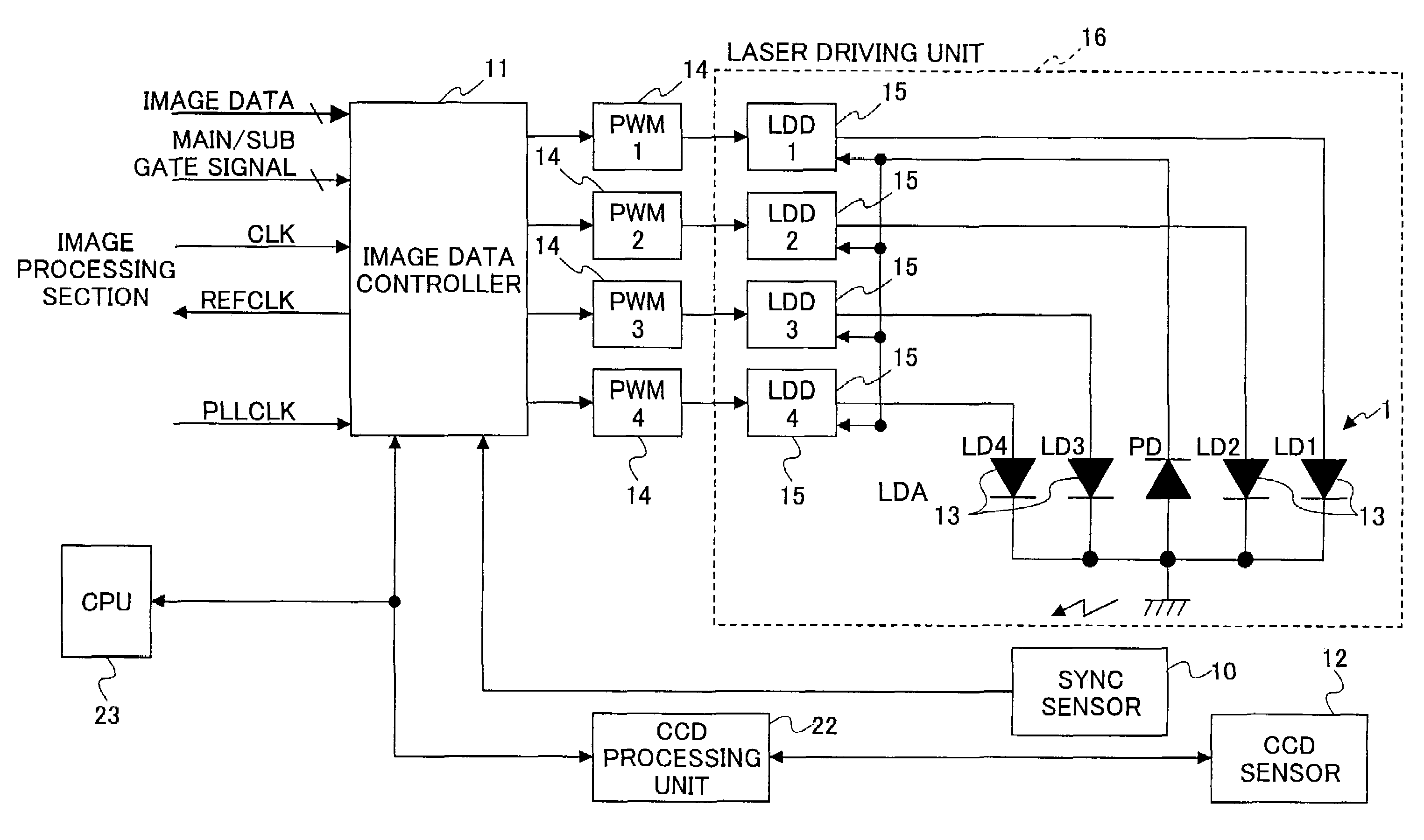
[0035]The scanning optical system shown in FIG. 1 includes a laser diode array 1, a collimator lens 2, an aperture 8, a cylindrical lens 3, a rotating polygon deflector 4, a pair of fθ lenses 5, a long sheet lens 6, a reflective mirror 9, and a photoconductor drum 7. Further, the scanning optical system has a synchronization detection system including a synchronization detection sensor 10, an image data controller 11, and a CCD area sensor 12.

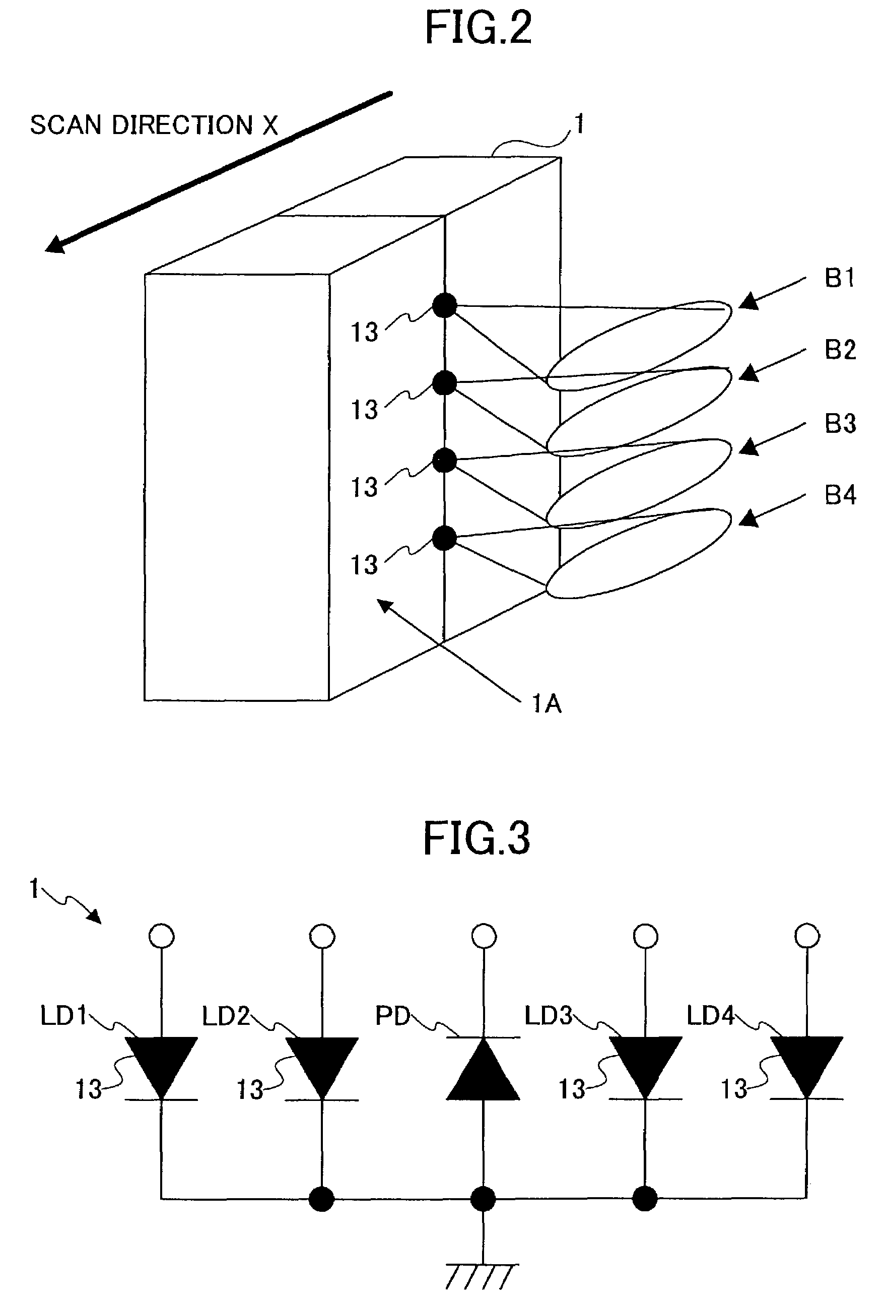
[0036]In the scanning optical system shown in FIG. 1, the laser diode array 1 includes four light emitting units packed in one chip to emit four laser beams. For example, the laser diode array 1 is a semiconductor laser chip having four laser units and emits four divergent laser beams.

[0037]The light emitting units are individually controllable when being modulated, and are arranged at approxim...

second embodiment

[0076]FIG. 12 is a perspective view showing a configuration of an image recording apparatus according to a second embodiment of the present invention. The configuration of the present embodiment is basically the same as that in the first embodiment. Below only the differences between then are described. Further, in the following description, the same reference numerals are used for the same components as in the first embodiment.

[0077]As illustrated in FIG. 12, the CCD area sensor 12 is arranged near the photoconductor drum 7 along the main scanning direction at a position before the starting scanning position.

[0078]The same as in the first embodiment, at the timing shown by the timing chart in FIG. 10, first the laser diodes LD1 through LD4 are driven to emit light on the CCD area sensor 12 simultaneously to calculate the image dot intervals in the main scan direction (X1, X2, X3), and from these calculated intervals, the light emission delays of LD2 through LD4 relative to LD1 are ...

third embodiment

[0079]FIG. 13 is a perspective view showing a configuration of an image recording apparatus according to a third embodiment of the present invention. The configuration of the present embodiment is basically the same as those in the previous embodiments. Below the differences between then are described. Further, in the following description, the same reference numerals are used for the same components as in the previous embodiments.

[0080]As illustrated in FIG. 13, the CCD area sensor 12 is arranged near the photoconductor drum 7 along the main scanning line at a position after the ending scanning position.

[0081]The same as in the previous embodiments, at the timing shown by the timing chart in FIG. 10, the laser diodes LD1 through LD4 are driven to emit light on the CCD area sensor 12 simultaneously to calculate the image dot intervals in the main scan direction (X1, X2, X3), and from these calculated intervals, the light emission delays of LD2 through LD4 relative to LD1 are determi...


PUM


Abstract

There is provided an image recording apparatus able to form images without fluctuation of image dot intervals in the main scan direction.
The image recording apparatus comprises a light emitting source including multiple light emitting units emitting laser beams, and a detection unit for detecting the laser beams and measuring intervals of the laser beams in the main scan direction. Based on the measured intervals of the laser beams in the main scan direction, light emission timings of the light emitting units are adjusted so that the intervals between each two image dots on the photoconductor in the main scan direction are not influenced by the interval fluctuation of the laser emitting units.

Description

BACKGROUND OF THE INVENTION[0001]1. Field of the Invention[0002]The present invention relates to a scanning optical system using a laser diode array, and an image recording apparatus including the scanning optical system.[0003]2. Description of the Related Art[0004]In an image recording apparatus including a scanning optical system, such as a laser printer, or a copier machine, high speeds of image formation and high image densities are desirable. It is known that this can be achieved by using a scanning optical system including a plurality of laser beams to scan the surface of a photoconductor medium at the same time, and, laser diode arrays are widely used in the scanning optical system to emit the laser beams.[0005]When using the laser diode arrays, in order that the scanning optical system forms scanning lines on the surface of the photoconductor medium having constant intervals, the laser diodes in a laser diode array, or a laser driving unit in which the laser diode array is i...

Claims


Application Information

Patent Timeline
IPC IPC(8): G06F15/00B41J2/44B41J2/47G02B26/10G03G15/04H04N1/036H04N1/113H04N1/23
CPCB41J2/473G03G15/04036G03G15/0435
Inventor NIITO, YOSHIHARU
Owner RICOH KK
Why Eureka
Try Eureka