Coated silver nanoparticles and manufacturing method therefor

a technology of silver nanoparticles and manufacturing methods, applied in the direction of electrically-conductive paints, conductive layers on insulating supports, conductors, etc., can solve the problems of insufficient examination or disclosure of their sintering temperature and electrical conductivity, and the inability to obtain coarse particles, so as to reduce energy and resource consumption. , the effect of reducing the amount o

Active Publication Date: 2012-02-23
YAMAGATA UNIVERSITY
View PDF7 Cites 34 Cited by
  • Summary
  • Abstract
  • Description
  • Claims
  • Application Information

AI Technical Summary

Benefits of technology

[0025]According to the present invention, coated silver nanoparticles can be provided that can be sintered in the vicinity of room temperature of 120° C. or lower, or even 100° C. or lower, thereby enabling the formation of an electrically conductive film or electrically conductive wiring even on a plastic substrate having low heat resistance such as PET or polypropylene.
[0026]In addition, the aforementioned complex compound can be synthesized in the absence of solvent and at a low temperature (room temperature). Moreover, coated silver nanoparticles can be directly obtained by thermally decomposing the complex compound at a low temperature in the vicinity of 100° C., and since there is no need to separately add a reducing agent as in the manner of other methods, both energy and resource consumption can be reduced considerably. The method of the present invention is suitable for industrial production.

Problems solved by technology

However, dispersibility of the resulting coated silver nanoparticles in solvent, their sintering temperature and their electrical conductivity are not adequately examined or disclosed.
However, when silver nanoparticles are simply attempted to be manufactured that have a small mean particle diameter, the particles end up aggregating (sintered) in the manufacturing process thereof due to the surface tension of the silver nanoparticles, thereby resulting in the problem of only being able to obtain coarse particles that do not demonstrate any further low-temperature sintering.

Method used


Image

  • Coated silver nanoparticles and manufacturing method therefor
  • Coated silver nanoparticles and manufacturing method therefor
  • Coated silver nanoparticles and manufacturing method therefor

Examples


example 1

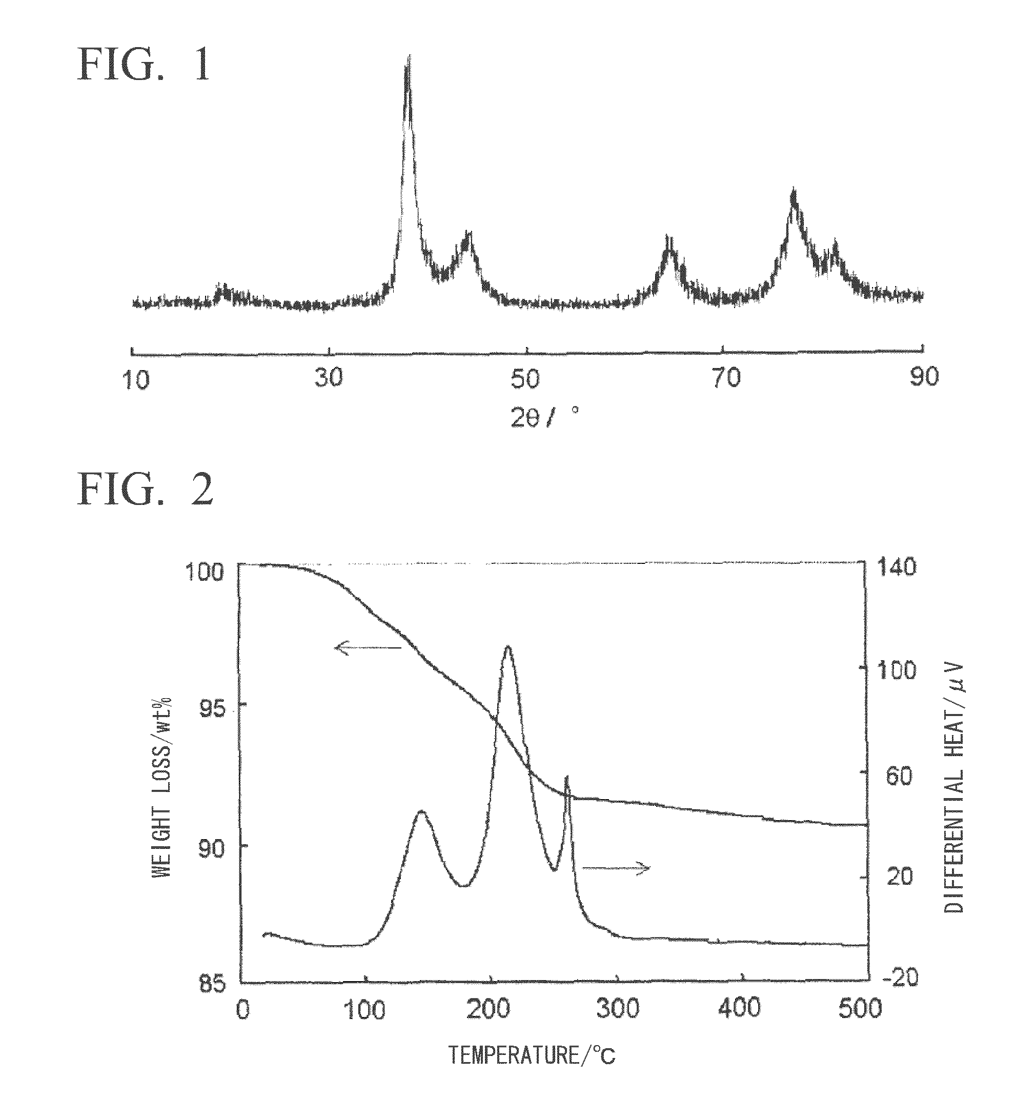
[0092]2.04 g (20.0 mmol) of N,N-dimethyl-1,3-diaminopropane (Tokyo Chemical Industry, special grade), 1.94 g (15.0 mmol) of n-octylamine (Kao, purity: 98%) and 0.93 g (5.0 mmol) of n-dodecylamine (Kanto Chemical, special grade) were mixed followed by the addition to this mixed solution of 6.08 g (20.0 mmol) of silver oxalate (synthesized from silver nitrate (Kanto Chemical, grade 1) and ammonium oxalate monohydrate or oxalic acid dihydrate (Kanto Chemical, special grade) and stirring for 3 minutes to prepare an oxalate ion-alkylamine-alkyldiamine-silver complex compound. When this was stirred for 20 to 30 minutes while heating at 95° C., a reaction accompanied by foaming of carbon dioxide was completed, and the reaction mixture changed to a suspension having a blue glossy color. When 10 mL of methanol (Kanto Chemical, grade 1) were added thereto and the precipitate obtained by centrifugal separation was air-dried, 4.62 g (97.0% yield based on silver) of a solid were obtained in the ...

example 2

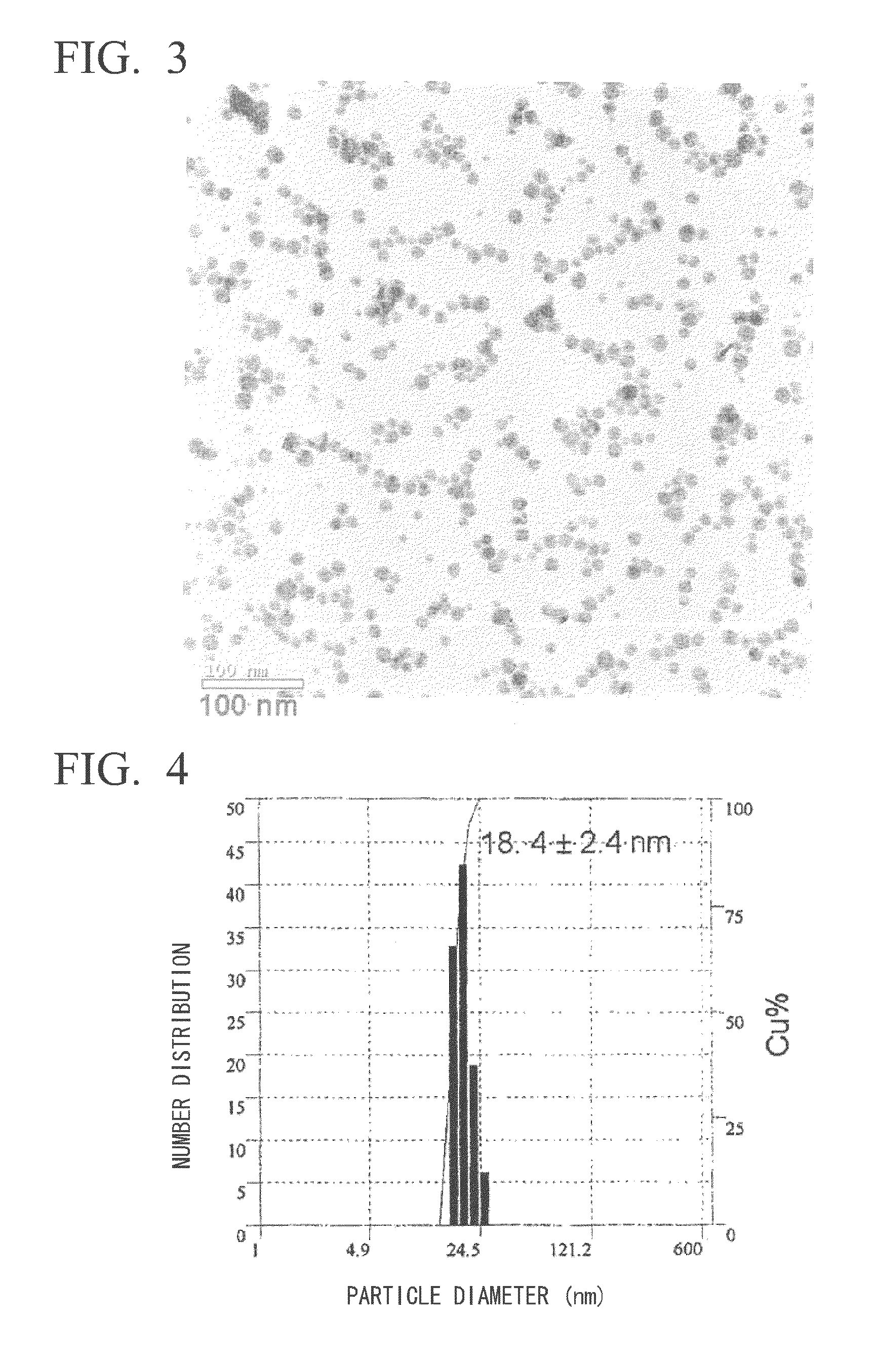
[0097]The dispersibility of the coated silver nanoparticles obtained in Example 1 in solvent was evaluated. As a result, the coated silver nanoparticles favorably dispersed in n-butanol (Kanto Chemical, special grade) and a mixed solvent of n-butanol and n-octane (Kanto Chemical, special grade). The resulting coated silver nanoparticles were determined to favorably disperse at a number average particle diameter of 18 nm based on dynamic light scattering particle size measurement (Otsuka Electronics ELS-Z2M) of the resulting n-butanol and n-octane mixed solvent dispersion (FIG. 4). In addition, dispersions of coated silver nanoparticles having concentrations of 30% by weight or more were also able to be prepared from the resulting solid, and based on the ultraviolet-visible absorption spectra (Shimadzu UV3150) of those dispersions, a surface plasmon band was observed that was derived from coated silver nanoparticles having a maximum wavelength of less than 400 nm. In addition, the di...

example 3

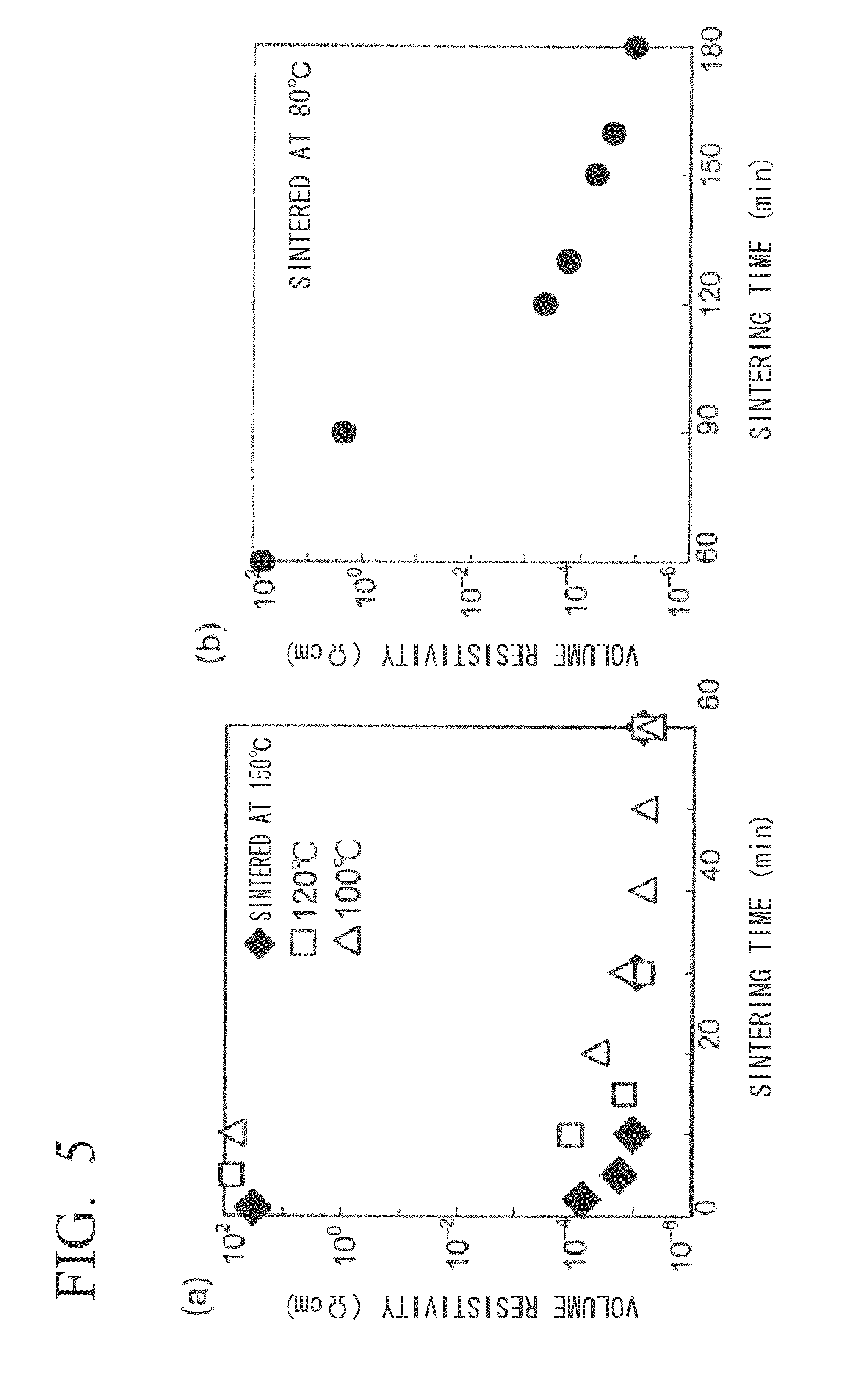
[0098]Low-temperature sinterability was evaluated for the coated silver nanoparticles obtained in Example 1. A spin-coated film of the coated silver nanoparticles was fabricated on a polyethylene terephthalate (PET) substrate (Fuji Film Axia, OHP sheet) using the n-butanol dispersion of coated silver nanoparticles prepared in Example 2. The coated substrate was heat-sintered at 60° C., 80° C., 100° C., 120° C. and 150° C. followed by measurement of the electrical resistance thereof (Kyowa Riken, K-705RS, four-point probe method) (FIG. 5, logarithmic scale displayed on vertical axis). In the case of sintering at 150° C., a favorable electrically conductive film (metal gloss film) having volume resistivity of 10−5 Ωcm to 10−6 Ωcm near that of metallic silver was obtained in 10 minutes (FIG. 5(a)). After heating for 30 minutes in the case of sintering at 120° C., or after heating for 40 minutes in the case of sintering at 100° C., volume resistivity of 10−5Ωcm to 10−6 Ωcm was reached (...


PUM

PropertyMeasurementUnit
mean particle diameteraaaaaaaaaa
temperatureaaaaaaaaaa
boiling pointaaaaaaaaaa

Abstract

The present invention provides coated silver nanoparticles for use as an electrically conductive material capable of sintering at lower temperatures that is able to be used even with flexible printed substrates having low heat resistance, and a manufacturing method therefor. The coated silver nanoparticles of the present invention have a mean particle diameter of 30 nm or less and are coated with protective molecules amine, and are characterized in that the weight loss rate when heated to 160° C. in thermogravimetric measurement is 30% or more. The coated silver nanoparticles of the present invention are also characterized in that a silver-colored sintered film can be formed by sintering at a temperature of 100° C. or lower for 1 hour or less. These coated silver nanoparticles are manufactured by mixing a silver compound that forms metallic silver when decomposed by heating, an alkylamine and an alkyldiamine to prepare a complex compound, and by thermally decomposing the silver compound by heating the complex compound.

Description

TECHNICAL FIELD[0001]The present invention relates to coated silver nanoparticles that have superior dispersibility in a solvent and demonstrate favorable electrical conductivity as a result of low-temperature sintering on a flexible printed substrate and the like, a manufacturing method therefor, and a sintered silver adherend using the same.[0002]The present application claims priority on the basis of Japanese Patent Application No. 2009-100926 filed in Japan on Apr. 17, 2009 and Japanese Patent Application No. 2010-047170 filed in Japan on Mar. 3, 2010, the contents of which are incorporated herein by reference.BACKGROUND ART[0003]Advances in the field of semiconductor devices and other electronic components along with the considerable development of printed wiring substrates on which these electronic components are mounted have been behind the remarkable progress achieved in the field of electronic devices. Since many of these electronic devices are required to be more compact, ...

Claims


Application Information

Patent Timeline
Patent Type & Authority Applications(United States)
IPC IPC(8): H01B1/22B22F1/00B22F1/0545B22F1/102B22F1/12B22F1/16B82B3/00B82Y99/00
CPCB22F1/0022B22F1/0062B22F9/30B22F2999/00B82Y30/00H05K1/097B22F2998/00B22F2301/255B22F2304/054H01B1/22B22F1/0545B22F1/102B22F1/00H01B5/14B22F1/16C09D5/24B05D5/12
Inventor KURIHARA, MASATOSAKAMOTO, MASAOMI
Owner YAMAGATA UNIVERSITY
Why Eureka
Try Eureka