
Color conversion filter and manufacturing method of the organic EL display

a technology of color conversion filter and organic el, which is applied in the direction of optical elements, instruments, coatings, etc., can solve the problems of insufficient conversion light intensity, breakage of lines, and reduced absorption of light to be absorbed, so as to prevent ink diffusion

Active Publication Date: 2012-11-06
SHARP KK
View PDF24 Cites 30 Cited by
  • Summary
  • Abstract
  • Description
  • Claims
  • Application Information

AI Technical Summary

Benefits of technology

[0018]Hence, a first object of this invention is to provide a color conversion filter manufacturing method using an inkjet method, which enables formation of a color conversion layer at desired positions even when a barrier wall is not formed separately. A second object of this invention is to provide an organic EL display manufacturing method that applies the above-described color conversion filter manufacturing method.
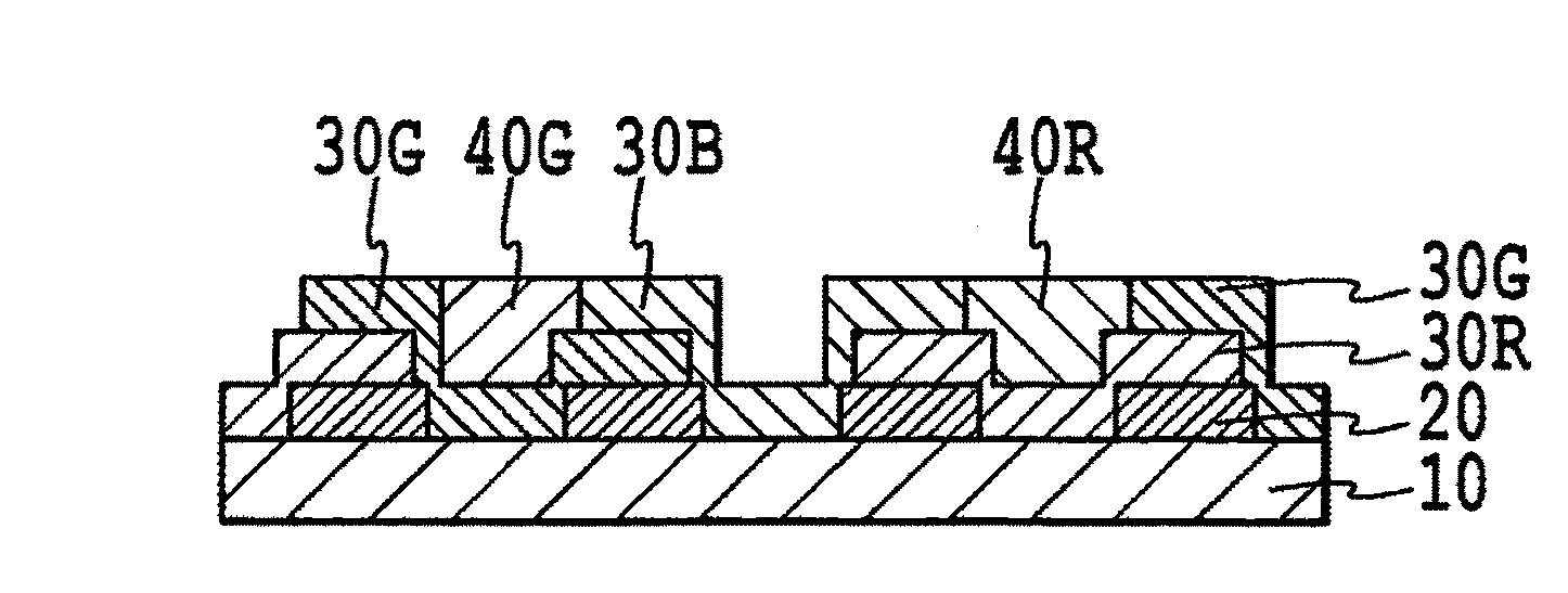
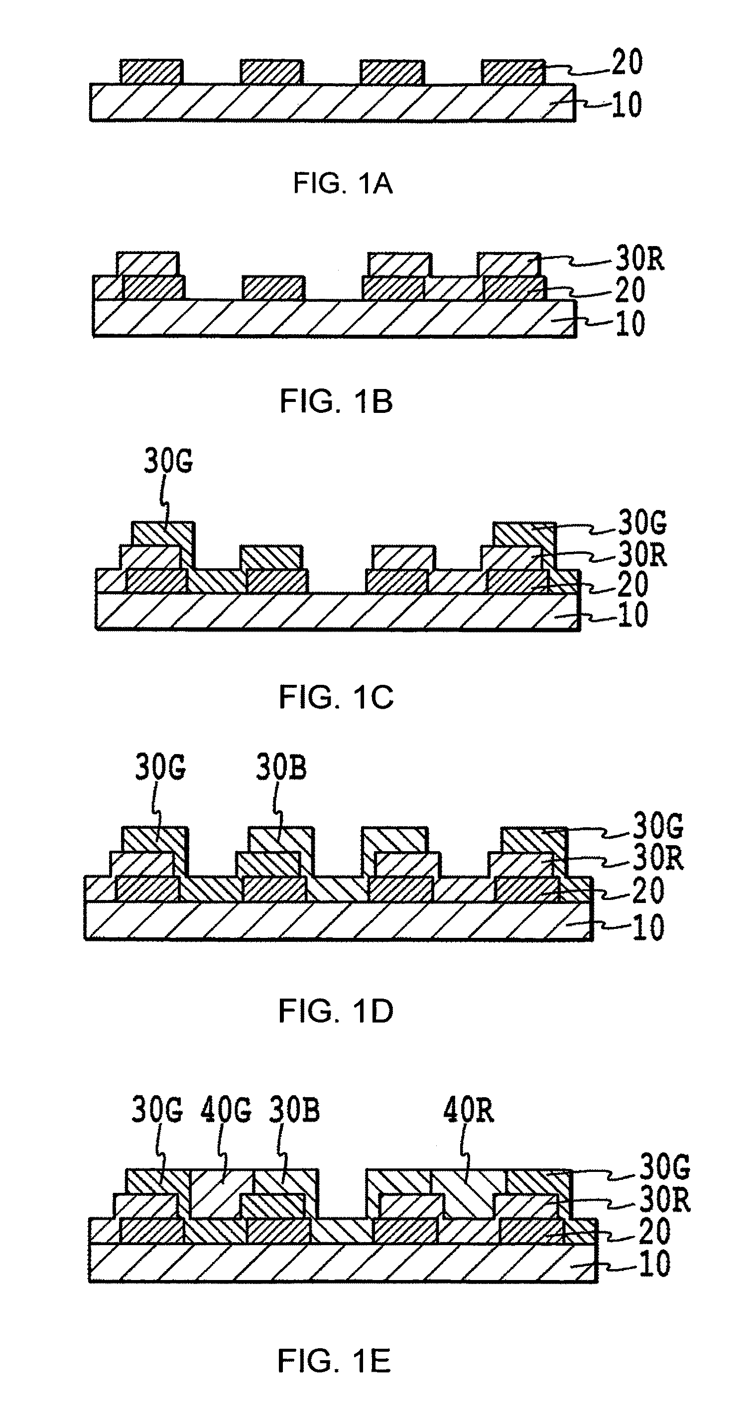
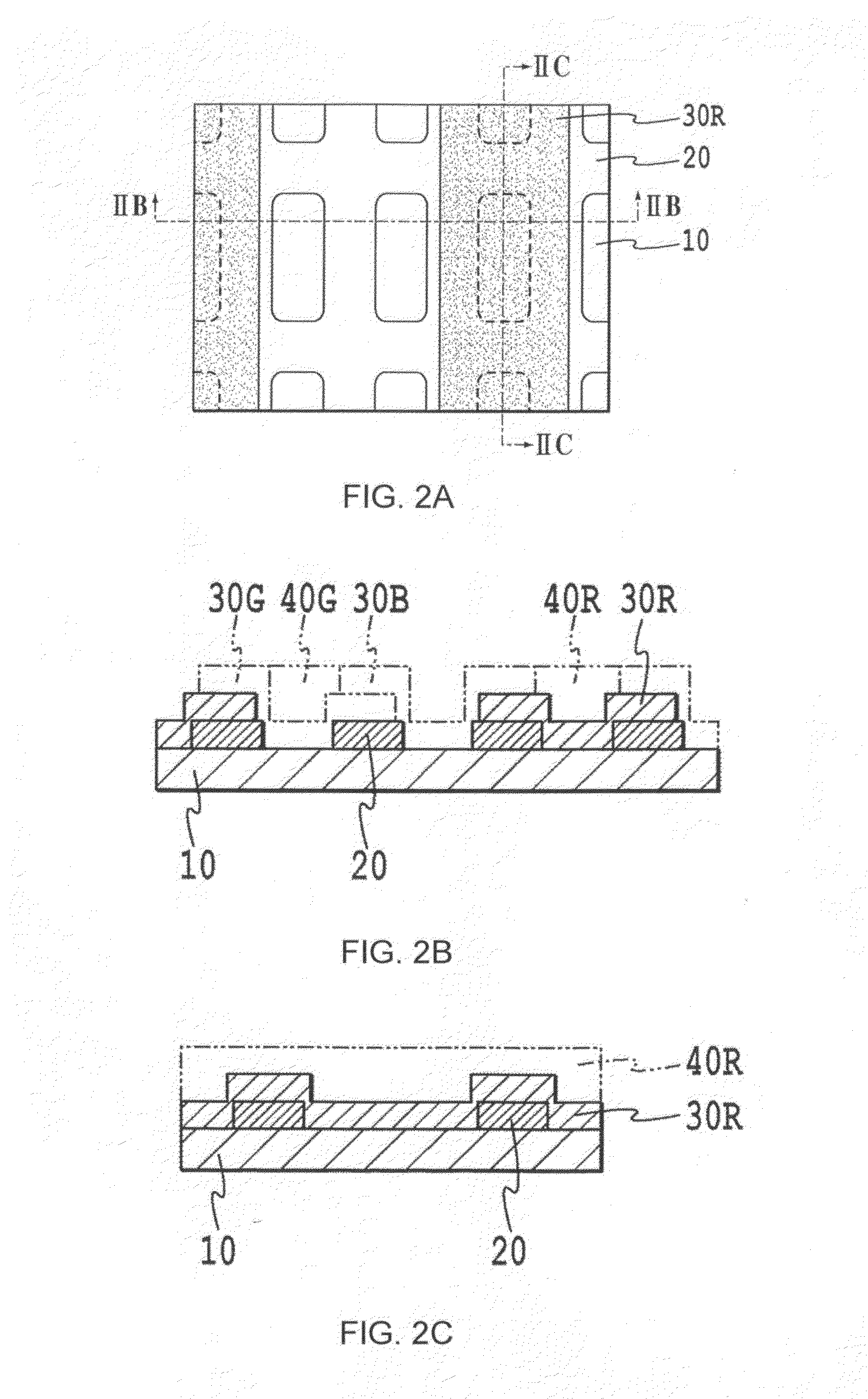
[0022]In this invention, by adopting a configuration described above, by layering a black matrix and at least two types of color filter layers in specific sites, the need to separately form barrier walls, which had been indispensable in inkjet methods proposed in the prior art, can be eliminated. Also, in a method of this invention, by being able to use a black matrix as a marker for positioning of an inkjet device in color filter layer patterning and color conversion layer formation, it is possible to form color conversion layers having high-resolution patterns with a resolution of 140 ppi or higher. Further, in a method of this invention, the film thickness of color filter layers as well as the black matrix film thickness can be used as the height of the barrier walls, so that barrier walls can be formed which more effectively prevent ink diffusion. And, a manufacturing method of this invention can avoid the above-described problems with evaporation deposition methods using metal masks. Further, by using this method it is possible to manufacture organic EL displays capable of high-resolution multicolor display.

Problems solved by technology

On the other hand, if the concentration of the color conversion material is lowered, absorptance of the light to be absorbed is reduced, and adequate converted light intensity is not obtained.
When a color conversion layer is used with the film thickness increased to approximately 10 μm in this way, there exist such problems as breakage of lines in electrode patterns at step portions, the difficulty of attaining high resolution, and, when combined with organic EL elements, changes in the properties of the organic EL layer due to residual water content or solvent in the color conversion layer, display defects, and similar.
In addition, from the standpoint of reducing dependence on the viewing angle, increasing the film thickness of the color conversion film is not preferable.
When forming the color conversion layer by evaporation deposition, the color conversion layer is formed over the entirety of the layer serving as the base, and so separation of the regions emitting light in each of the three primary colors (red, green, and blue) is not possible.
Consequently there is a limit to the fineness of the metal mask.
Further, because wraparound of evaporated material behind the metal mask occurs, there is a limit to the fineness of the pattern formed using a metal mask.
In actuality, the limit is a resolution level of 150 pixels per inch (ppi), and formation of patterns at resolutions exceeding this is difficult.
Further, as substrates grow larger there are greater demands on the rigidity of the metal mask, and when rigidity is insufficient, mask bending poses a problem.
Because of this problem also, it is difficult to increase substrate sizes.
In addition, reductions in yield occur due to pattern shifting when placing the metal mask on the substrate for film deposition and other problems, and so there is the further problem that cost reduction is difficult.
Separate formation of barrier walls entails an increase in the number of manufacturing processes, and a consequent increase in manufacturing costs.
However, the separate formation of markers also entails an increase in the number of manufacturing processes, and a consequent increase in manufacturing costs.

Method used


Image

  • Color conversion filter and manufacturing method of the organic EL display
  • Color conversion filter and manufacturing method of the organic EL display
  • Color conversion filter and manufacturing method of the organic EL display

Examples


example 1

Color Conversion Filter

[0115]Color Mosaic CK-7001 (manufactured by Fuji Film Electronic Materials, Co., Ltd.) was applied onto 1737 glass (manufactured by Corning Inc.) 200 mm in length by 200 mm in width by 0.7 mm thick, and photolithography was used to form a black matrix having a plurality of rectangular openings. The black matrix had a film thickness of 1 μm. Each of the rectangular openings, equivalent to subpixels, was 131 μm in the length direction and 37 μm in the width direction, and the intervals between adjacent rectangular openings were 10 μm in both the length and width directions.

[0116]Next, Color Mosaic CK-7001 (manufactured by Fuji Film Electronic Materials, Co., Ltd.) was applied, and photolithography used, to form a red color filter layer comprising a plurality of stripe-shape portions extending in the length direction. Each of the plurality of stripe-shape portions was formed so as to overlap with portions of the adjacent black matrix extending in the length direc...

example 2

[0129]Except for the fact that the film thickness of the black matrix was made 2 μm, the procedure of Example 1 was repeated to manufacture an organic EL display. In the intermediate structure of the color filter in this example, the barrier walls formed by layering two types of color filter layers in portions of the black matrix extending in the length direction each have a height of 3 μm.

example 3

[0130]Except for the facts that the film thickness of the black matrix was made 2.5 μm, and that the film thickness of each of the color filter layers (R, G, B) was made 1.5 μm, the procedure of Example 1 was repeated to manufacture an organic EL display. In the intermediate structure of the color filter in this example, the barrier walls formed by layering two types of color filter layers in portions of the black matrix extending in the length direction each have a height of 4 μm.


PUM


Abstract

A process for producing a color conversion filter uses an ink jet recording method, which can form a color conversion layer at a desired position without the need to separately form partition walls, and a process for producing an organic EL display. The process for producing a color conversion filter includes forming a black matrix having a plurality of opening parts on a transparent substrate, forming at least two types of color filter layers independently of each other on a black matrix to which dissimilar color filter layers are adjacent, to form a partition wall, at least two of the color filter layers being superimposed on top of each other, and forming a color conversion layer by ink jet recording onto at least one of the color filter layers.

Description

TECHNICAL FIELD[0001]This invention relates to a method of forming a color conversion filter. In particular, this invention relates to a method for manufacturing a color conversion filter including a color conversion layer having a high-resolution pattern. Also, this invention relates to a method for manufacturing an organic EL display, which includes the above-described color conversion filter, and which outputs at least one color from among the three primary colors through a color conversion layer.BACKGROUND ART[0002]In recent years in the display field, multicolor emissive displays have been developed which are capable of multicolor or full-color display. In particular, considerable efforts have been made to develop high-resolution multicolor emissive EL displays, which can make effective use of the characteristics of organic EL elements. This is because in organic EL elements high current densities can be obtained at low applied voltages, and consequently high brightness and hig...

Claims


Application Information

Patent Timeline
Patent Type & Authority Patents(United States)
IPC IPC(8): H01L21/00
CPCG02B5/201G02B5/223H01L27/322H01L51/5284H10K59/38H10K50/865
Inventor NAKAMURA, HIDEYOKANAI, NAOYUKI
Owner SHARP KK
Learn More