Magnetic head positioning control method and magnetic head positioning control apparatus

US20090244768A1Inactive Publication Date: 2009-10-01FUJITSU LTD

Image

  • Magnetic head positioning control method and magnetic head positioning control apparatus
  • Magnetic head positioning control method and magnetic head positioning control apparatus
  • Magnetic head positioning control method and magnetic head positioning control apparatus

Examples


first embodiment

[0055]In the present invention, in case where RRO is great, the magnetic head positioning control apparatus may correct a target value so that the magnetic head does not follow the RRO. For this reason, a positional trajectory is produced for each track, an error in which an observation position “y” is subtracted from a target position “r” is determined as a positional error and the positional error may be recorded in advance in an RRO target-value correction table 411 as an RRO target-value correction amount. The magnetic head positioning control apparatus may read the RRO target-value correction amount corresponding to the current sector number from the RRO target-value correction table 411 and changes the target position based on the read RRO target-value correction amount.

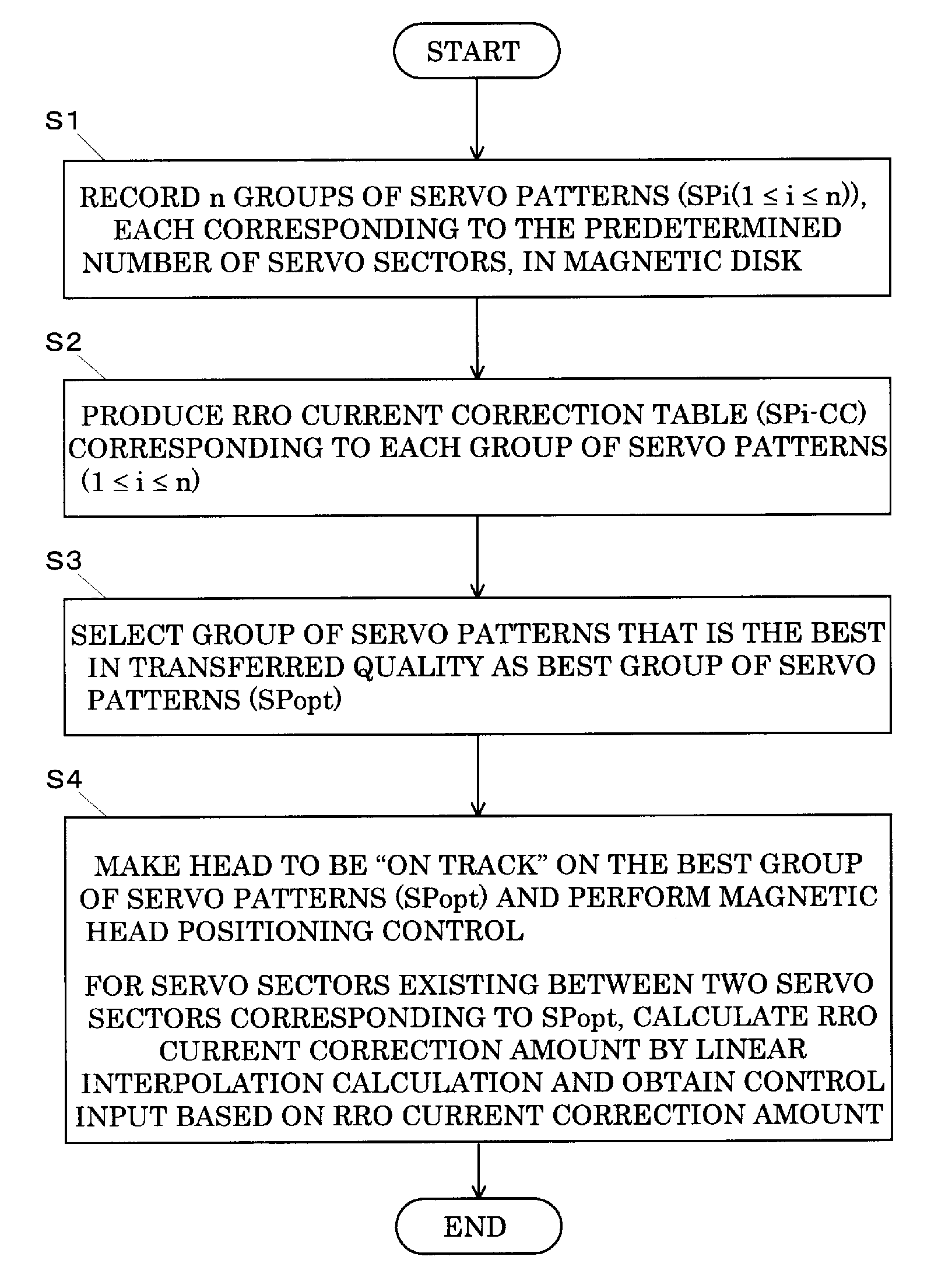
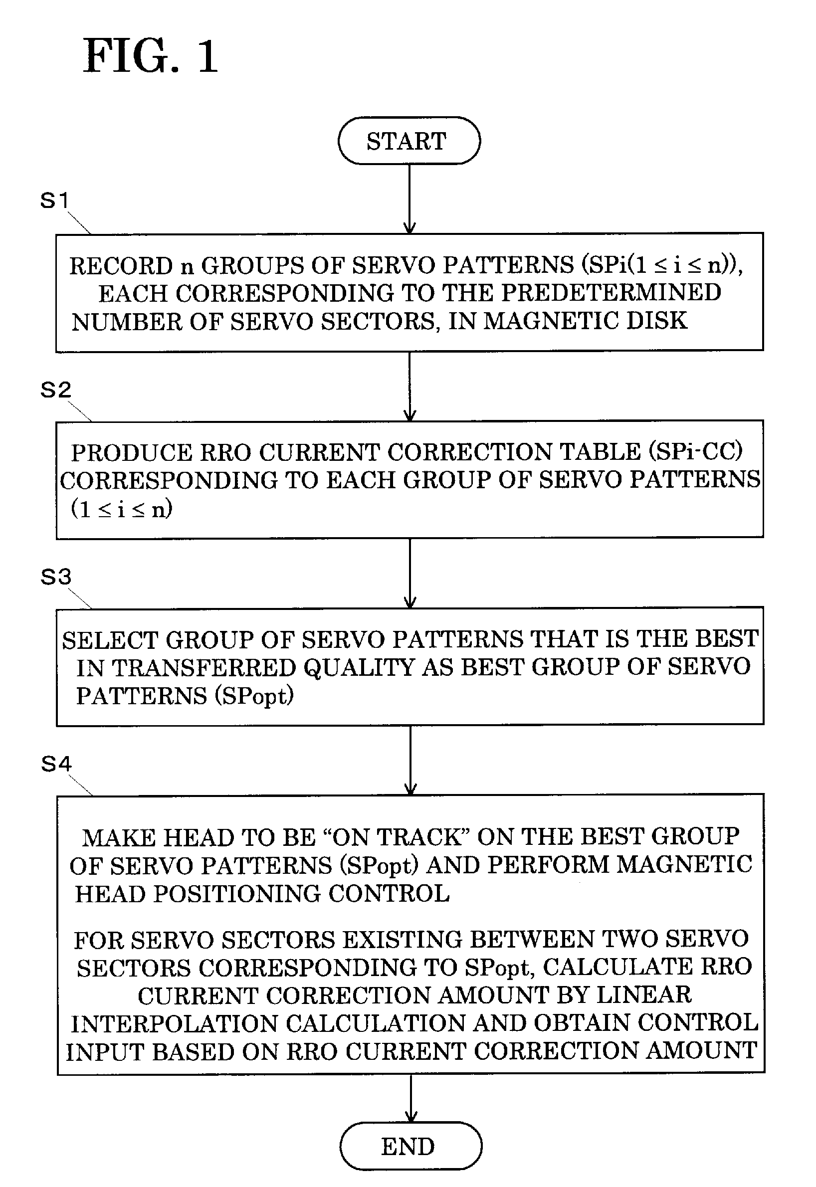
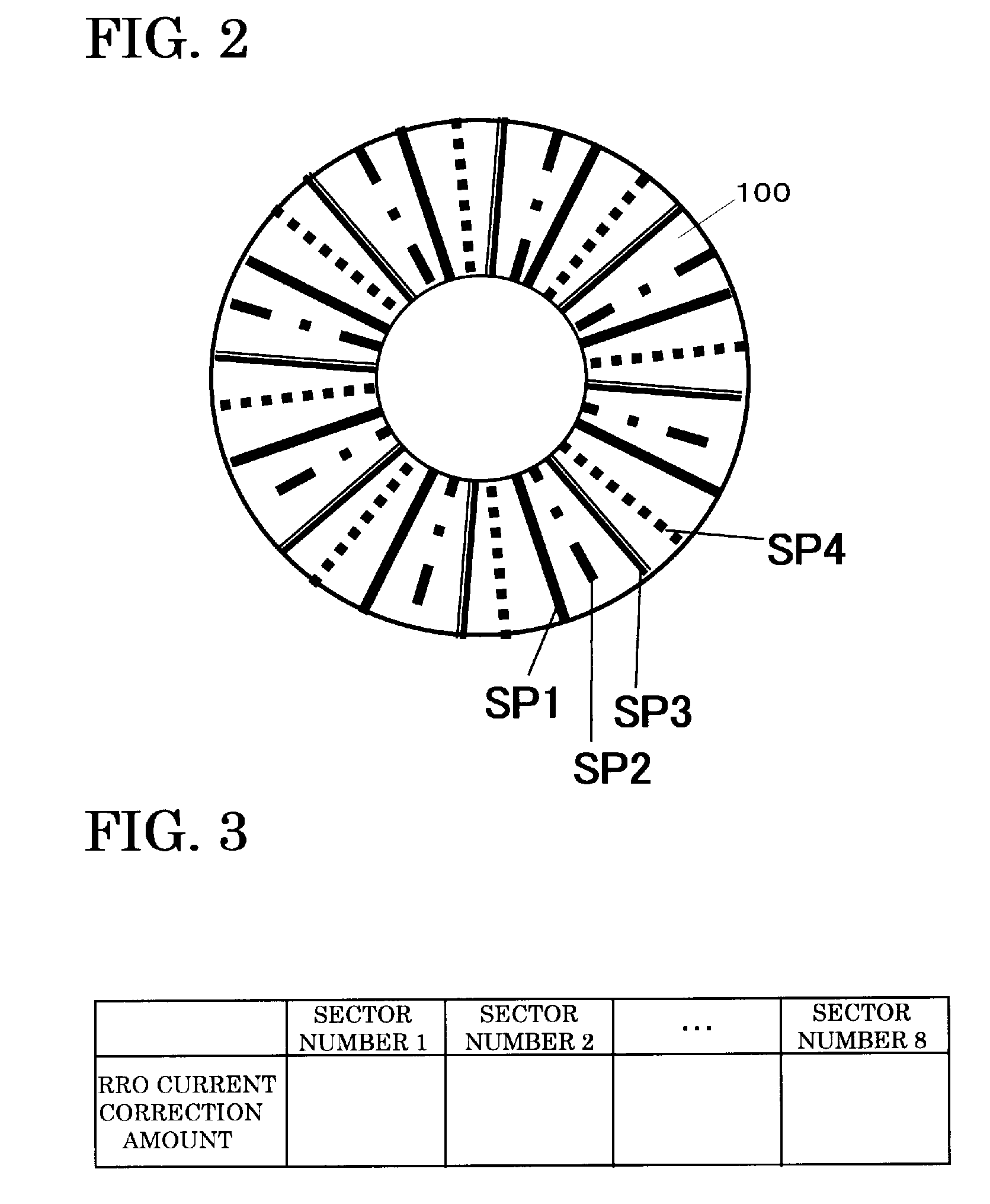
[0056]In the first embodiment of the present invention, for example, four groups of servo patterns (SP1, SP2, SP3 and SP4) shown in FIG. 2 are recorded in a magnetic disk. The magnetic head positioning control ...

second embodiment

[0068]For example, the magnetic head positioning control apparatus in the present invention calculates the control input U(20) corresponding to the servo sector with a servo sector number “20” corresponding to the SPi by the following equation 4.

U(20)=ulfb(20)+ulcc(20)  Equation 4.

[0069]The ulfb (20) is the output of the low frequency band FB controller 401 corresponding to the servo sector with a servo sector number “20.” The ulcc (20) is an RRO current correction amount corresponding to the servo sector in the SP1-CC.

[0070]The magnetic head positioning control apparatus in the second embodiment of the present invention calculates the control signal U(20, k) corresponding to the servo sector (S (20, k)) corresponding to the groups of servo patterns excluding the SP1 existing between the servo sector with a servo sector number “20” and the servo sector with a servo sector number “21” by the following equation 5.

[0071]U(20, k)=ulfb (20)+uhfb (20, k)+uhcc (20, k) . . . . Equation 5. W...


PUM


Abstract

N groups of servo patterns, each corresponding to the predetermined number of servo sectors, are recorded in a magnetic disk. The magnetic head positioning control apparatus of the present invention produces an RRO current correction table corresponding to each group of servo patters and selects the group of servo patterns that is the best in transferred quality of the sevro pattern as SPopt. For servo sectors (target servo sectors) corresponding to other groups of servo patterns and existing between two adjacent servo sectors corresponding to the SPopt, the magnetic head positioning control apparatus calculates an RRO current correction amount corresponding to the target servo sector by a linear interpolation calculation using the RRO current correction amount corresponding to each of the adjacent servo sectors in the RRO current correction table corresponding to the SPopt to perform the magnetic head positioning control based on the calculated RRO current correction amount.

Description

CROSS-REFERENCE TO RELATED APPLICATIONS[0001]This application claims the conventional priority based on Japanese Application No. 2008-077027, filed on Mar. 25, 2008, the disclosures of which are incorporated herein by reference.BACKGROUND OF THE INVENTION[0002]1. Field of the Invention The present invention relates to a magnetic head positioning control method and a magnetic head positioning control apparatus, and in particular, to a magnetic head positioning control method and a magnetic head positioning control apparatus performing a magnetic head positioning control between servo sectors accurately.[0003]2. Description of the Related Art[0004]For a head positioning control in a magnetic disk apparatus, a magnetic head in the magnetic disk apparatus reads a servo pattern recorded on the magnetic disk to be positioned. For example, when a servo pattern shown in FIG. 8B is recorded in a servo sector 101 on a magnetic disk 100 shown in FIG. 8A, the magnetic head is positioned based o...

Claims


Application Information

Patent Timeline
01 Oct 2009
Publication
US20090244768A1
IPC
G11B5/596
CPC
G11B5/59627; G11B21/10; G11B21/02; G05B13/02; G05B11/36
Inventors
MARUYAMA, TSUGITO