Liquid ejection apparatus

a liquid ejection and apparatus technology, applied in the direction of printing, inking apparatus, etc., can solve the problems of deterioration of the piezoelectric element, increase in power consumption, and difficulty in determining the start position of the slight vibration, so as to reduce the heat generation of the liquid ejection head, reduce the increase in power consumption, and facilitate the timing

Active Publication Date: 2017-02-07
BROTHER KOGYO KK
View PDF15 Cites 0 Cited by
  • Summary
  • Abstract
  • Description
  • Claims
  • Application Information

AI Technical Summary

Benefits of technology

[0009]Accordingly, an aspect of the disclosure relates to a liquid ejection apparatus capable of easily determining the timing when a meniscus of liquid in a nozzle is slightly vibrated, with reduced increase in power consumption, reduced heat generation of a liquid ejection head, and reduced deterioration of an actuator.

Problems solved by technology

However, since the recording start position is changed depending upon the dot pattern information, complicated processings may be required for setting the slight-vibration start position.
This operation may cause increase in power consumption, heat generation of the recording head, and deterioration of the piezoelectric element, for example.

Method used


Image

  • Liquid ejection apparatus
  • Liquid ejection apparatus
  • Liquid ejection apparatus

Examples


first embodiment

[0033]Hereinafter, there will be described a first embodiment.

Overall Construction of Printer

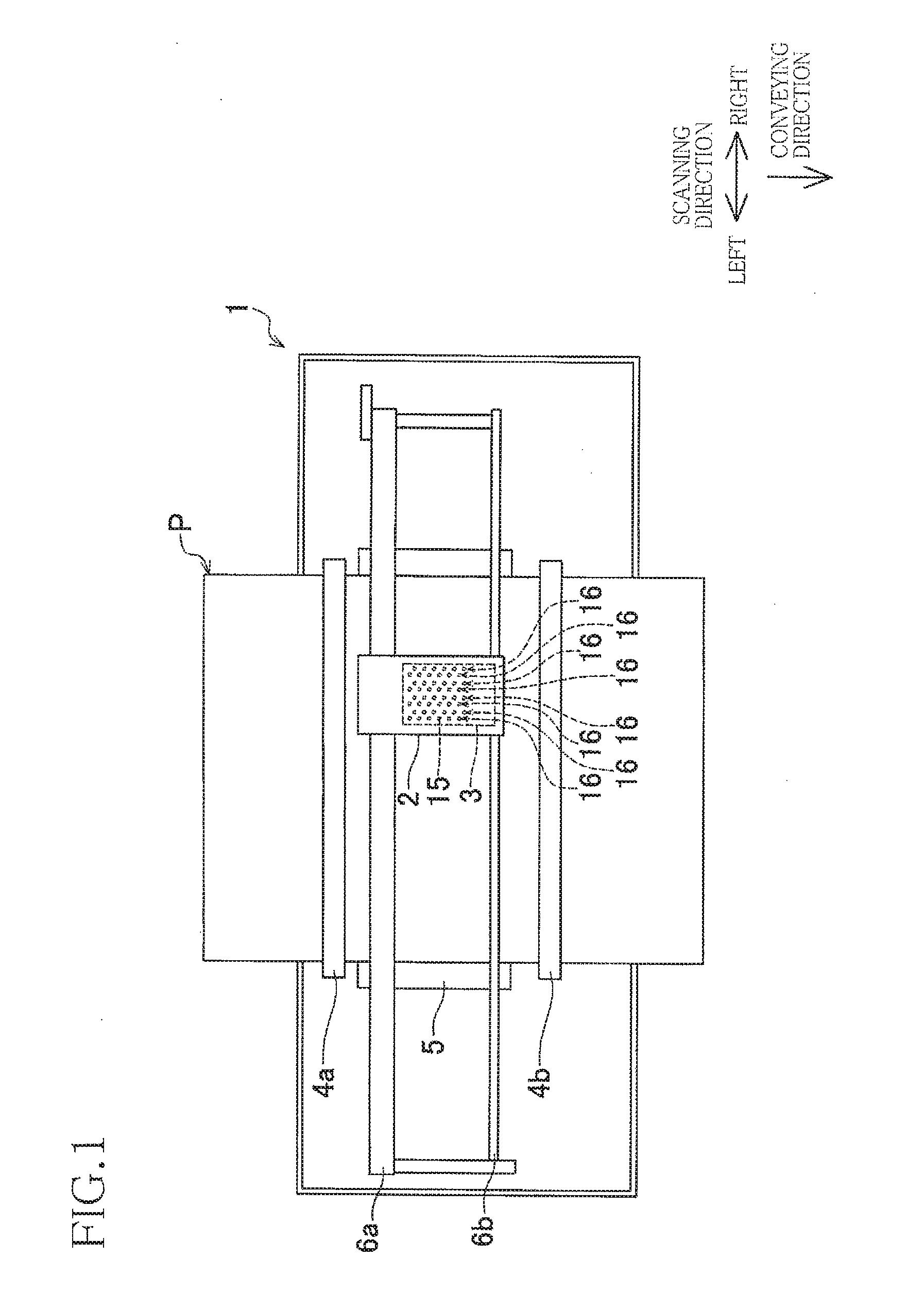
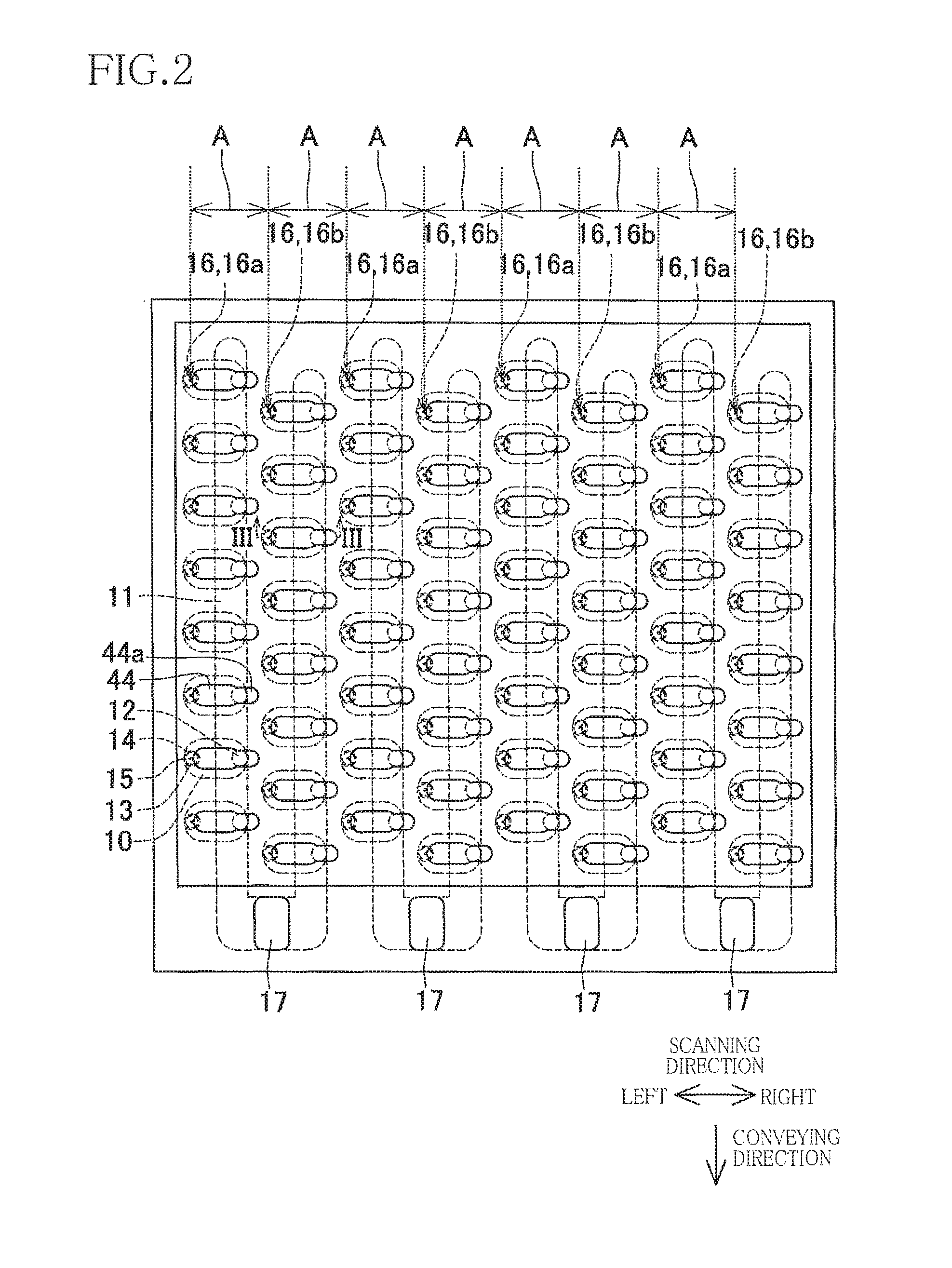
[0034]As illustrated in FIG. 1, a printer 1 according to a first embodiment includes a carriage 2, an ink-jet head 3, conveying rollers 4a, 4b, and a platen 5. The carriage 2 is movably supported by guide rails 6a, 6b extending in a scanning direction. The carriage 2 is connected to a carriage motor 61 (see FIG. 3) via a belt and pulleys, not illustrated. The carriage 2 is driven by the carriage motor 61 so as to be reciprocated in the scanning direction. In the following description, the right and left sides are defined with respect to the scanning direction as illustrated in FIG. 1.

[0035]The ink-jet head 3 is mounted on the carriage 2 and ejects ink from a multiplicity of nozzles 15 formed in a lower surface of the ink-jet head 3. The conveying roller 4a is disposed upstream of the carriage 2 in a direction perpendicular to the scanning direction. The conveying roller 4b is disposed downst...

second embodiment

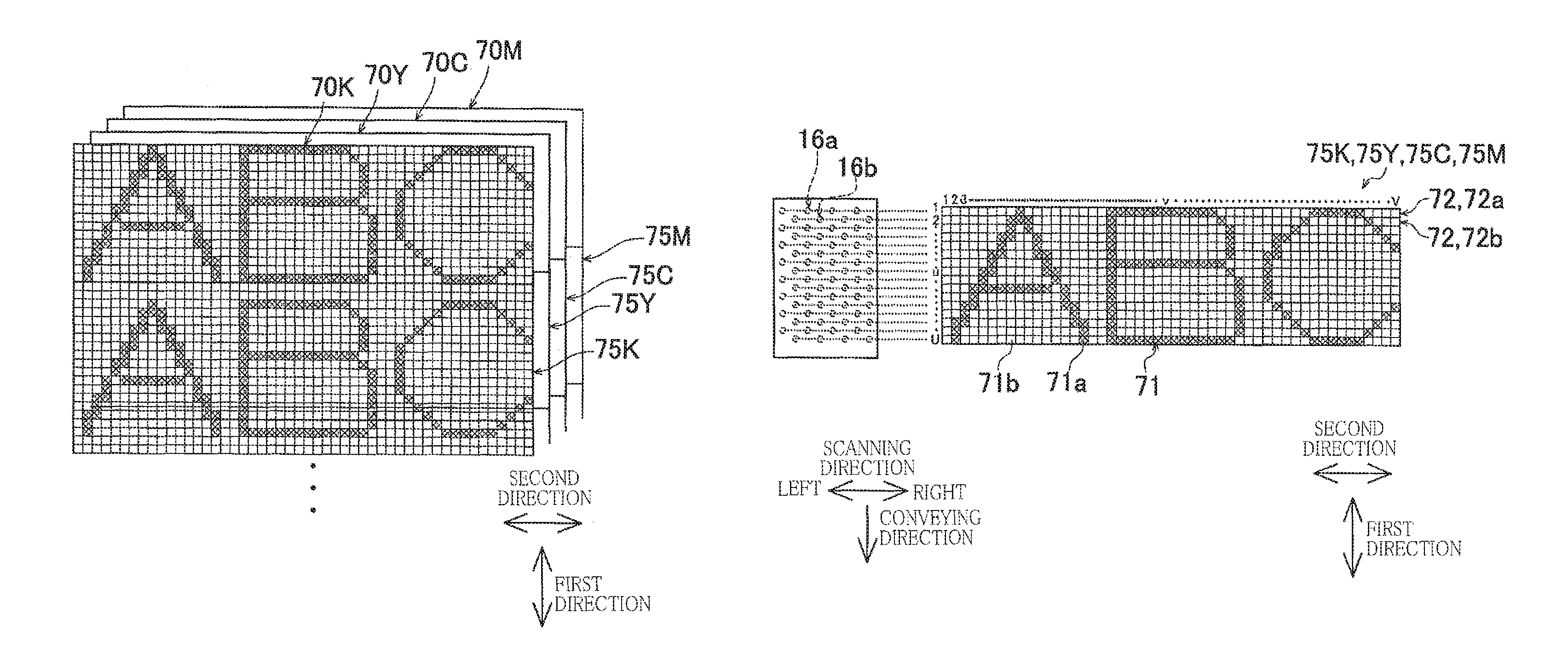
[0076]There will be next explained a second embodiment. As illustrated in FIG. 10, a printer 100 according to the second embodiment includes four ink-jet heads 101K, 101Y, 101C, 101M instead of the carriage 2 and the ink-jet head 3 of the printer 1 according to the first embodiment. It is noted that the same reference numerals as used in the first embodiment are used to designate the corresponding elements of the second embodiment, and an explanation of which is dispensed with.

[0077]Each of the ink-jet heads 101K, 101Y, 101C, 101M is what is called a line head extending in the scanning direction throughout the entire length of the recording sheet P. The ink-jet heads 101K, 101Y, 101C, 101M are arranged in the conveying direction. Each of the ink-jet heads 101K, 101Y, 101C, 101M ejects ink from a multiplicity of nozzles 115 formed in a lower surface of the ink-jet head. The nozzles 115 of each of the ink-jet heads 101K, 101Y, 101C, 101M are arranged in the scanning direction so as to...

first modification

[0105]In a first modification, as illustrated in FIG. 15, slight vibration pattern information 300 is used for all the four colors. In the slight vibration pattern information 300, third information 301a do not overlap each other in position in the second direction between each of slight vibration information rows 302a containing the odd-numbered nozzles 15 (as another example of the first nozzle row) from the upstream side in the conveying direction among the nozzle rows 16 and each of slight vibration information rows 302b containing the even-numbered nozzles 15 (as another example of the second nozzle row) from the upstream side in the conveying direction among the nozzle rows 16. In this configuration, the driving cycles in which the slight vibration signals D2 are transmitted do not overlap between each two nozzles 15 adjacent to each other in the conveying direction in each of the nozzle rows 16.

[0106]Here, unlike the first modification, if the meniscuses of the ink are slight...


PUM


Abstract

A liquid ejection apparatus stores ejection pattern information and slight vibration pattern information indicating two-dimensional arrangements of ejection information and slight vibration information, respectively. A controller transmits an ejection signal when the ejection information at a first position in the ejection pattern information is first information and when the slight vibration information at a second position in the slight vibration pattern information is third information or fourth information. The controller transmits a slight vibration signal the ejection information at the first position is second information and when the slight vibration information at the second position is the third information. The controller transmits a non-vibration signal when the ejection information at the first position is the second information and when the slight vibration information at the second position is the fourth information.

Description

CROSS REFERENCE TO RELATED APPLICATION[0001]The present application claims priority from Japanese Patent Application No. 2015-074655, which was filed on Mar. 31, 2015, the disclosure of which is herein incorporated by reference in its entirety.BACKGROUND[0002]Technical Field[0003]The following disclosure relates to a liquid ejection apparatus configured to eject liquid from nozzles.[0004]Description of the Related Art[0005]There are known ink-jet recording apparatuses including a carriage and a recording head mounted on the carriage, and configured to control the recording head to eject ink droplets from nozzles of the recording head while moving the carriage in a main scanning direction. A first example of the ink-jet recording apparatuses creates dot pattern information for one line, store the created dot pattern information into an output buffer, and then set a recording start position that is a position at which ink is to be ejected first in a printing area corresponding to the ...

Claims


Application Information

Patent Timeline
Patent Type & Authority Patents(United States)
IPC IPC(8): B41J2/045
CPCB41J2/04588B41J2/04586B41J2/04581B41J2/04596B41J2002/14459B41J2202/21
Inventor SEKIGUCHI, YASUHIROITO, YUICHINODSU, TOMOHIRO
Owner BROTHER KOGYO KK
Why Eureka
Try Eureka