System for controlling brain machine interfaces and neural prosthetic systems

a neural prosthetic and brain machine technology, applied in the field of robotic control systems, can solve the problems of limited joint space prosthetic control capacity, no known prosthetic control system has been proposed, and fewer advances, and achieve the effect of minimizing the cost potential

Active Publication Date: 2017-02-14
HRL LAB
View PDF2 Cites 6 Cited by
  • Summary
  • Abstract
  • Description
  • Claims
  • Application Information

AI Technical Summary

Benefits of technology

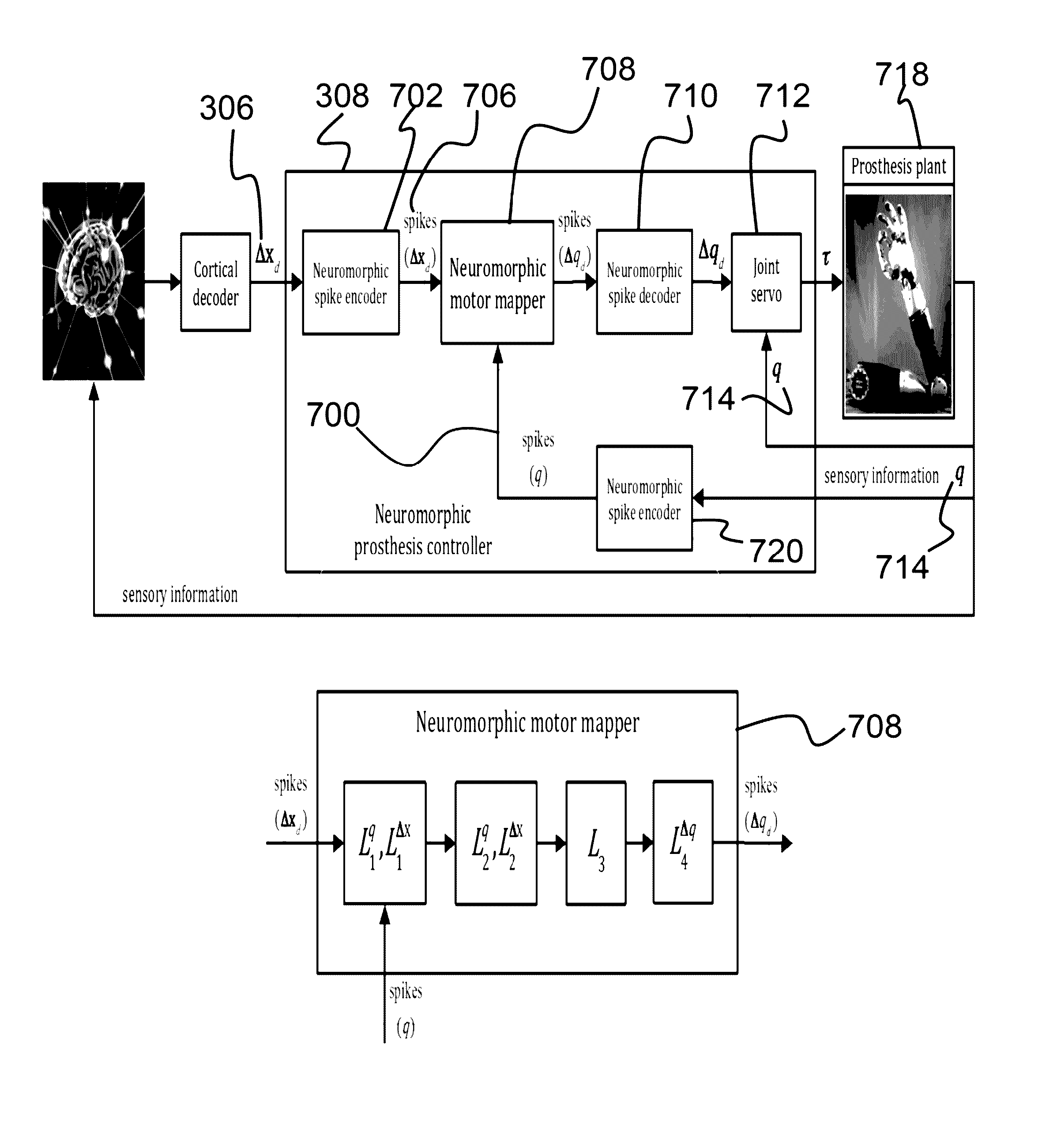
[0018]Further, in executing the motion commands, the motion commands are executed as torque commands that generate a desired task space control while minimizing the cost potential.

Problems solved by technology

However, with regard to prosthetic device control there have been fewer advances, with most approaches rooted in conventional robotic control.
To date, no known prosthetic control system has been proposed which uses a task / posture decomposition.
Joint space prosthetic control is limited in this capacity due to its reliance on inverse kinematics solutions.
Thus, again, there is no known system that integrates a sensorimotor controller, in addition to the prosthetic controller.

Method used


Image

  • System for controlling brain machine interfaces and neural prosthetic systems
  • System for controlling brain machine interfaces and neural prosthetic systems
  • System for controlling brain machine interfaces and neural prosthetic systems

Examples


Embodiment Construction

[0046]The present invention relates to a robotic control system and, more particularly, to a system for controlling robotic prosthetic devices given motor intent inferred from neuroimaging data. The following description is presented to enable one of ordinary skill in the art to make and use the invention and to incorporate it in the context of particular applications. Various modifications, as well as a variety of uses in different applications will be readily apparent to those skilled in the art, and the general principles defined herein may be applied to a wide range of aspects. Thus, the present invention is not intended to be limited to the aspects presented, but is to be accorded the widest scope consistent with the principles and novel features disclosed herein.

[0047]In the following detailed description, numerous specific details are set forth in order to provide a more thorough understanding of the present invention. However, it will be apparent to one skilled in the art th...


PUM


Abstract

Described is a system for controlling a torque controlled prosthetic device given motor intent inferred from neuroimaging data. The system includes at least one torque controlled prosthetic device operably connected with one or more processors. Further, the system is configured to receive neuroimaging data of a user from a neuroimaging device and decode the neuroimaging data to infer spatial motion intent of the user, where the spatial motion intent includes desired motion commands of the torque controlled prosthetic device represented in a coordinate system. The system thereafter executes, with a prosthesis controller, the motion commands as torque commands to cause the torque controlled prosthetic device to move according to the spatial motion intent of the user.

Description

GOVERNMENT RIGHTS[0001]This invention was made with government support under U.S. Government Contract Number HR0011-09-C-0001. The Government has certain rights in the invention.CROSS-REFERENCE TO RELATED APPLICATIONS[0002]This is a non-provisional patent application of U.S. Provisional Application No. 61 / 903,538, filed Nov. 13, 2013, entitled, “A control and simulation architecture for application to brain machine interfaces and neural prosthetic systems.”[0003]This is ALSO a non-provisional patent application of U.S. Provisional Application No. 61 / 903,526, filed Nov. 13, 2013, entitled, “A goal-oriented sensorimotor controller for controlling musculoskeletal simulations with neural excitation commands.”BACKGROUND OF THE INVENTION[0004](1) Field of Invention[0005]The present invention relates to a robotic control system and, more particularly, to a system for controlling robotic prosthetic devices given motor intent inferred from neuroimaging data.[0006](2) Description of Related A...

Claims


Application Information

Patent Timeline
Patent Type & Authority Patents(United States)
IPC IPC(8): A61F2/72A61F2/68A61F2/54A61F2/70B25J13/08
CPCA61F2/68A61F2/54A61F2/72A61F2002/704B25J13/087A61F2002/701B25J13/00A61B5/055G06F3/00A61B2576/026A61B5/4851G16H30/40A61B5/389A61B5/369
Inventor DE SAPIO, VINCENTSRINIVASA, NARAYAN
Owner HRL LAB
Why Eureka
Try Eureka