Hook latch fitted with a positioning device and a method for assembling such a latch

a positioning device and latch technology, applied in the field of hook latches, can solve the problems of significant increase in the amount of fuel consumed by the apparatus, significant reduction in aerodynamics, and increase in aerodynamic drag, so as to achieve the effect of reducing tim

Active Publication Date: 2017-02-14
LISI AEROSPACE
View PDF16 Cites 41 Cited by
  • Summary
  • Abstract
  • Description
  • Claims
  • Application Information

AI Technical Summary

Benefits of technology

[0022]By virtue of these provisions, a simple screwing or unscrewing operation of the screw enables the adjustment of an angle formed by the handle and the adapter. Said device does not require the structures of the apparatus to be developed in any way and enables adjustment operations to be performed on the fasteners of the fixed structure.
[0061]By virtue of these provisions, the unscrewing operation for the hook performed by an operator cannot be excessive, i.e. cannot cause the rod of the hook to become dislodged, said dislodging representing a considerable loss of time when installing the latch.
[0072]By virtue of these provisions, the flushness of the upper surface of the latch in relation to the skin of the apparatus can be adjusted in a simple and quick manner, and the aerodynamics of the apparatus can thus be optimised.

Problems solved by technology

However, due to the various manufacturing and assembly tolerances, it appears that the upper surface 51 of the latch 11 is often, as shown in this example, in a non-flush position, i.e. the ends of the handle 19 are not aligned with the aerodynamic surface 53 of the apparatus, which represents a considerable reduction in aerodynamics, an increase in aerodynamic drag and therefore a significant increase in the amount of fuel consumed by the apparatus.
This type of latch, although frequently used, therefore creates a major technical problem for one of ordinary skill in the art.
This leads to a non-negligible loss of time, and therefore a lengthy downtime for the apparatus.

Method used


Image

  • Hook latch fitted with a positioning device and a method for assembling such a latch
  • Hook latch fitted with a positioning device and a method for assembling such a latch
  • Hook latch fitted with a positioning device and a method for assembling such a latch

Examples


Embodiment Construction

[0085]In these figures, identical elements keep the same reference numbers.

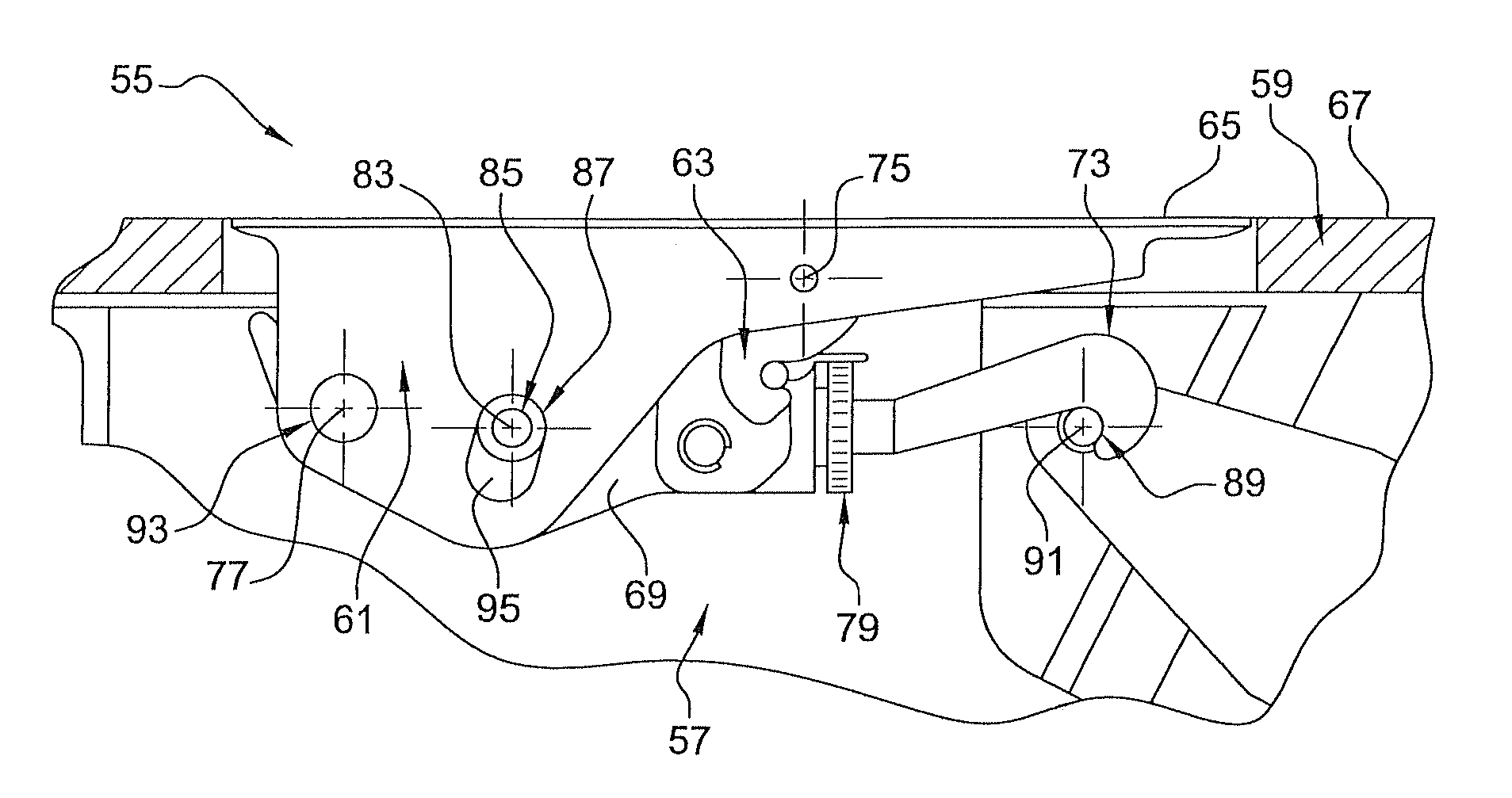
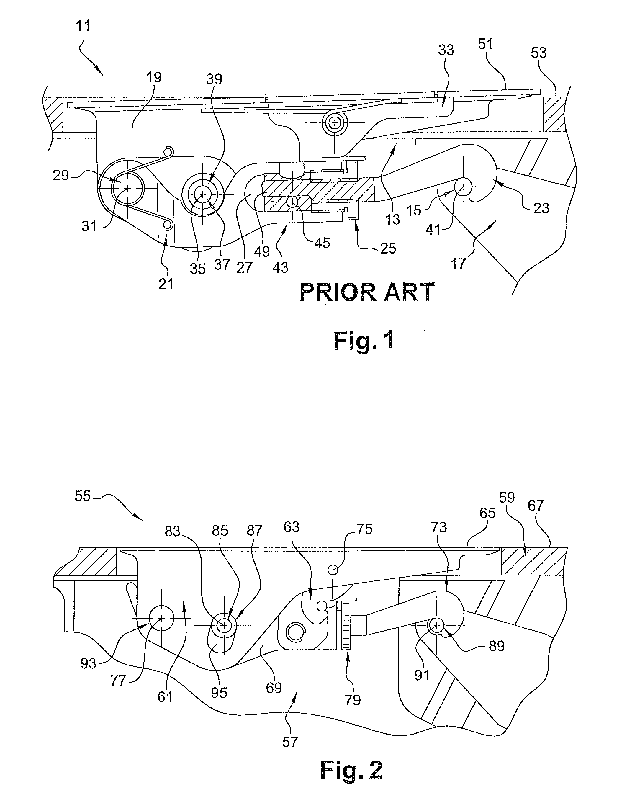
[0086]FIG. 2 represents, in a schematic manner, a side view of a hook latch 55 according to one embodiment of the invention in its environment and in a locked flush position.

[0087]In this example, the latch 55 has a plane of symmetry passing through its centre.

[0088]The latch 55 is configured so as to lock and unlock a mobile structure 57 on a fixed structure 59 of an apparatus such as an aircraft. In this example, the apparatus is an aeroplane and the mobile structure 57 is a radome.

[0089]The latch 55 has a handle 61 comprising a trigger 63. The handle 61 has an upper surface65 intended to be positioned flush with an aerodynamic surface 67, commonly called a skin, of the fixed structure 59, in addition to two lateral flat surfaces substantially perpendicular to the upper surface 65.

[0090]The latch 55 also comprises an adapter 69 extending, in its locked position, along direction substantially parallel to tha...


PUM


Abstract

The invention relates to a hook latch (73) configured so as to lock and unlock a mobile structure on a fixed structure of a vehicle, said latch havingan adapter (69) fitted with a hook (73) capable of fastening a keeper,a handle comprising a trigger,on the handle, a second pivot connection axis,on the trigger, at least one hook capable of fastening at least one protrusion (125) of a bracket (121) connected to the adapter,a third pivot connection axis, around which the handle and the adapter are guided in rotation in relation to each other, andcharacterised in that it comprises an adjustment device for adjusting the flushness of the upper surface of the handle in relation to the aerodynamic surface, said device comprisingthe bracket (121),a screw (129) capable of being screwed and unscrewed within a first tapped recess of the adapter.

Description

TECHNICAL FIELD OF THE INVENTION[0001]This invention relates to a hook latch fitted with a positioning device. The technical field of the invention relates, in a general manner, to that of locking and unlocking devices. More particularly, the invention relates to hook latches intended for locking and unlocking a mobile structure on a fixed structure of a vehicle, for example an aircraft-type apparatus.TECHNOLOGICAL BACKGROUND OF THE INVENTION[0002]In the prior art, the technical teachings of documents U.S. Pat. Nos. 5,984,382A, 6,343,815B1, 6,382,690B1 and 7,131,672B2 are known to disclose hook latches.[0003]Typically, such latches can either be connected to the fixed structure of the apparatus and capable of fastening and maintaining its mobile structure, or be connected to its mobile structure and capable of fastening its fixed structure to attach said structure.[0004]FIG. 1 represents, in a schematic manner, a cross-section of a hook latch 11 according to one embodiment from the ...

Claims


Application Information

Patent Timeline
Patent Type & Authority Patents(United States)
IPC IPC(8): E05C5/00E05C19/12E05C19/14B65D45/00E05C19/10B64D29/06B65D45/30B65D45/32E05B63/06
CPCE05C19/145B64D29/06E05B63/06Y10T24/45435F16B45/00
Inventor DEFRANCE, VINCENTLUNEAU, ETIENNE
Owner LISI AEROSPACE
Why Eureka
Try Eureka