Connection element for a support frame system

a technology of connecting elements and support frames, applied in the direction of elongated construction elements, rod connections, fastening means, etc., can solve the problems of complex and expensive known approaches, and it is not easy to connect the sections of known support frames

Active Publication Date: 2017-02-14
LIEBHERR TRANSPORTATION SYST
View PDF22 Cites 1 Cited by
  • Summary
  • Abstract
  • Description
  • Claims
  • Application Information

AI Technical Summary

Benefits of technology

[0005]It is therefore the object of the present invention to further develop a connection element and a support frame system of the initially named kind in an advantageous manner, in particular such that support frame elements can be connected to one another simply and reliably.
[0008]A connection of the support frame elements is possible in a non-cutting manner, reliable in processing and secure against vibration, with the support frame elements being non-releasably or releasably connectable to one another by means of the connection element. Angular connections from 0° to 360° are also possible in continuous form since the part elements configured in U shape can be correspondingly positioned and set by their shape.

Problems solved by technology

It has been found to be disadvantageous in the previously known approaches for the purpose of support frame systems that the known approaches are complex and expensive or also can only be positioned with respect to one another with a great effort without corresponding apparatus.
It is also not easily possible to connect the sections of known support frame systems to one another, releasably or unreleasably, in a non-cutting manner, reliable in processing and secure against vibration.

Method used


Image

  • Connection element for a support frame system
  • Connection element for a support frame system
  • Connection element for a support frame system

Examples


Embodiment Construction

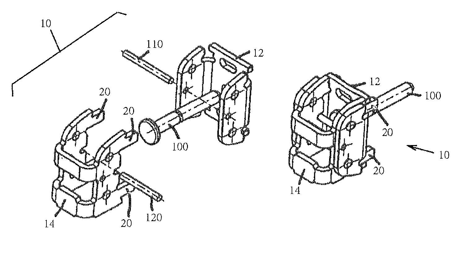
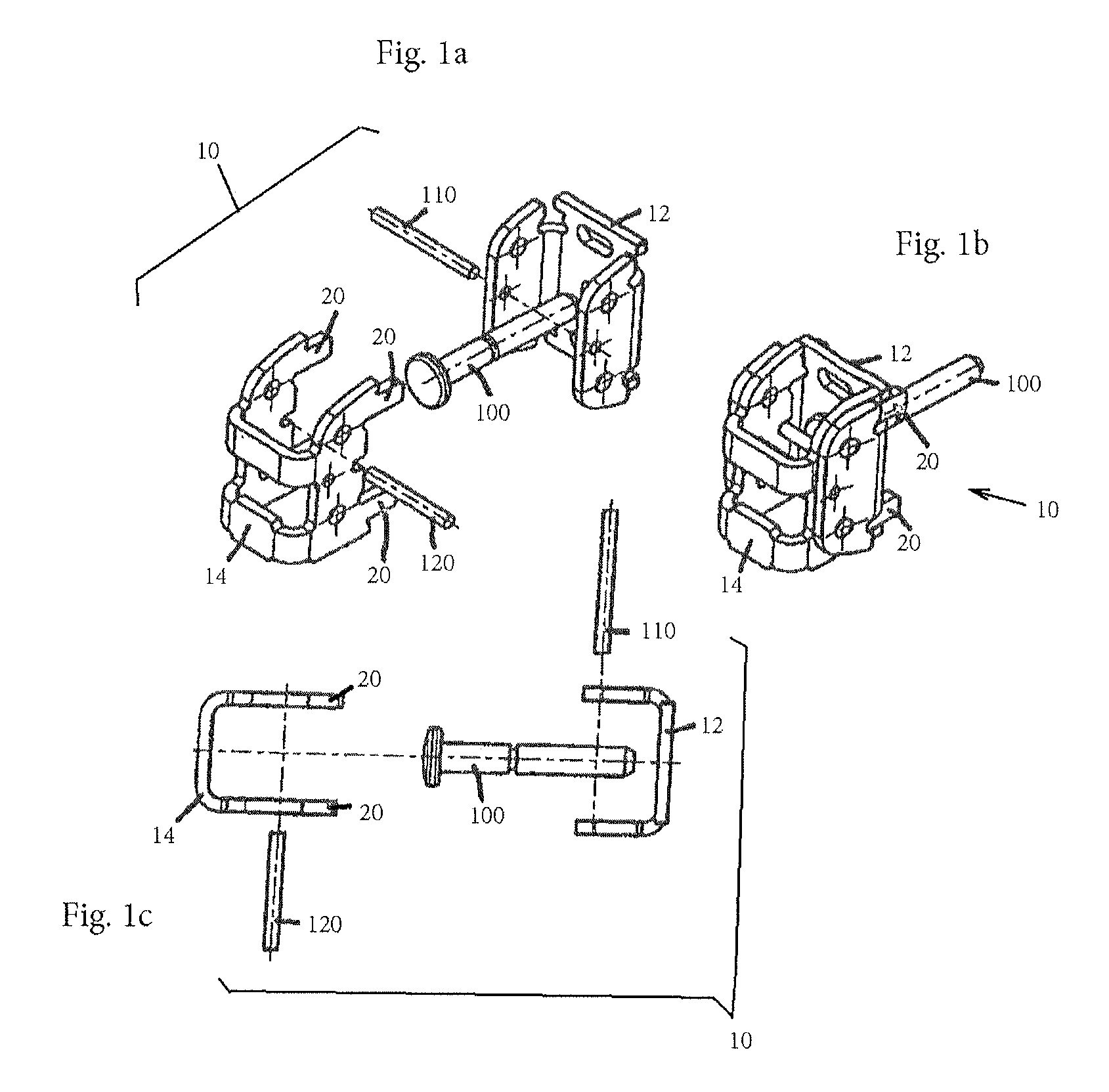
[0027]FIGS. 1a-c show several views, including an exploded representation and an assembled state, an embodiment of a variable connection element 10 with a closing eye bolt 100 in accordance with the invention.

[0028]The variable connection element 10 in this respect generally serves as a universal connection element for primarily rectangular hollow sections.

[0029]In this respect, only one single connection element size is advantageously required per hollow section cross-section size in order to be able to realize continuously, non-releasably or releasably, angular connections of 0° to 360°.

[0030]Support frame skeletons which are based on this variable section connection system can be directly provided with paneling, insertion elements, modular units and the like since the connection elements are invisibly integrated into the hollow sections, and thus planar, throughgoing support surfaces free of steps and overhangs can be realized.

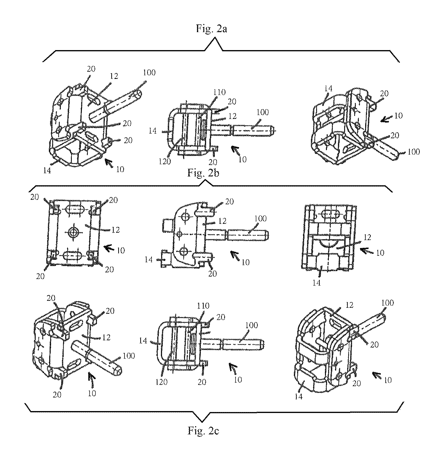
[0031]Each connection element 10 (cf. also FIG. 2 and...


PUM


Abstract

A connection element for a support frame system includes at least two part elements configured substantially in U shape and joinable together in mirror-inverted form. The elements can be plugged into one another in mirror-inverted form, with the first part element connectable to at least one fastening element and with the second part element connectable to at least one positioning element and / or having at least one positioning element.

Description

BACKGROUND OF THE INVENTION[0001]The present invention relates to a connection element for a support frame system, as well as to a support frame system having at least two support frame elements, and having at least one connection element.[0002]Support frame systems in the intended form of use such as skeleton support frames are in particular formed by rectangular aluminum hollow sections which are joined together by means of weld connections.[0003]The use of so-called ITEM sections and of corresponding connection elements or the use of gusset plates and angular elements is also known.[0004]It has been found to be disadvantageous in the previously known approaches for the purpose of support frame systems that the known approaches are complex and expensive or also can only be positioned with respect to one another with a great effort without corresponding apparatus. It is also not easily possible to connect the sections of known support frame systems to one another, releasably or unr...

Claims


Application Information

Patent Timeline
Patent Type & Authority Patents(United States)
IPC IPC(8): F16B7/04F16S3/08F16B7/18
CPCF16B7/04F16B7/0446F16B7/18F16B7/042Y10T403/7075
Inventor GABRIEL, ROMAN
Owner LIEBHERR TRANSPORTATION SYST
Why Eureka
Try Eureka