Spool valve and lubricating oil supply device

a technology of lubricating oil and spool valve, which is applied in the direction of fluid couplings, gearings, couplings, etc., can solve the problems of insufficient supply of lubricating oil and the spool may be stuck, and affect the durability of the object to be lubricated

Active Publication Date: 2017-02-14
AISIN AW CO LTD
View PDF9 Cites 0 Cited by
  • Summary
  • Abstract
  • Description
  • Claims
  • Application Information

AI Technical Summary

Benefits of technology

[0005]It is a main object of the spool valve and the lubricating oil supply device according to the present invention to secure sufficient output even if a spool is stuck.
[0009]an opening of the second output port is formed in such a shape that a width of the opening becomes gradually smaller in a direction of movement of the spool in which distribution of the output to the first output port is increased.
[0010]The spool valve according to the present invention includes the hollow portion formed with the input port, the first output port, and the second output port, and the spool capable of sliding within the hollow portion and having the plurality of lands. The spool valve is configured to distribute input to the input port to the first output port and the second output port in accordance with the proportion of distribution which matches the position of the spool. The opening of the second output port is formed in such a shape that the width of the opening becomes gradually smaller in the direction of movement of the spool in which distribution of the output to the first output port is increased. Consequently, in the case where foreign matter is caught between the opening of the second output port and the edge portion of the land along with movement of the spool in the direction in which distribution of the output to the first output port is increased, the spool is stuck after the foreign matter is moved to the distal-end portion of the opening of the second output port at which the opening is narrowest, and therefore the second output port is open only slightly. As a result, sufficient communication between the input port and the first output port can be secured to secure sufficient output to the first output port even if the spool is stuck.
[0011]In the spool valve according to the present invention configured as described above, the second output port may be a drain port; and output from the first output port may be adjusted by discharging to the drain port a part of the input to the input port. Consequently, it is possible to secure sufficient output to the output port while suppressing discharge to the drain port even if the spool is stuck.
[0012]In the spool valve according to the present invention, in addition, the opening of the second output port may be formed with a constant width portion of the same width with respect to the direction of movement of the spool, and a tapered portion that becomes gradually narrower as the tapered portion extends away from the constant width portion. Consequently, the constant width portion can secure the area of communication through the second output port even if the opening of the second output port is formed with the tapered portion.
[0018]In the lubricating oil supply device according to the present invention, the spool valve has the input port which receives the lubricating oil pumped by the discharge pressure of the line pressure, the first output port which outputs the lubricating oil to the object to be lubricated, and the second output port formed as the drain port, and functions to adjust the flow rate of the lubricating oil to be output from the first output port by distributing the hydraulic oil input to the input port to the first output port and the drain port. Thus, sufficient output to the first output port can be secured to sufficiently lubricate the object to be lubricated even if the spool is stuck.

Problems solved by technology

In the spool valve, however, the spool may be stuck if the liquid that flows into and out of the ports and the liquid chamber contains foreign matter such as dirt and such foreign matter is caught between the edge of the land of the spool and the port of the housing.
If a spool is stuck with a control pressure port (output port) for supplying lubricating oil to the objects to be lubricated unable to open sufficiently, supply of lubricating oil may be insufficient to adversely affect the durability of the objects to be lubricated.

Method used


Image

  • Spool valve and lubricating oil supply device
  • Spool valve and lubricating oil supply device
  • Spool valve and lubricating oil supply device

Examples


Embodiment Construction

[0029]A preferred embodiment of the present invention will be described below.

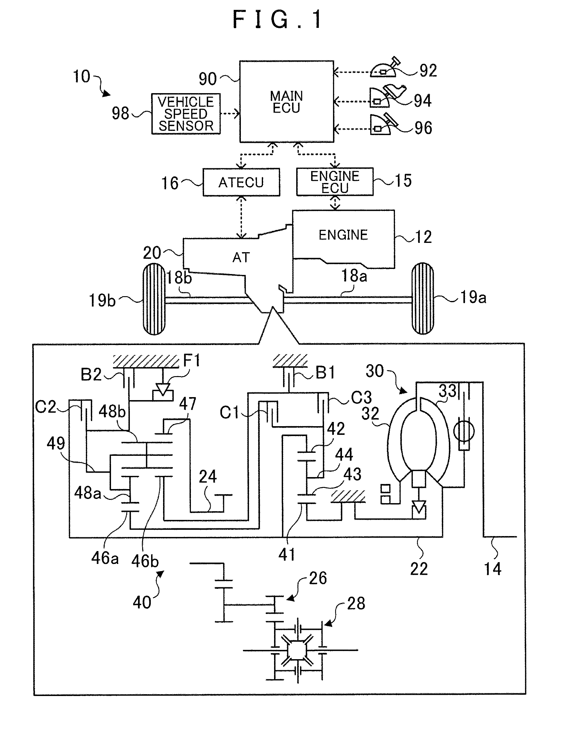
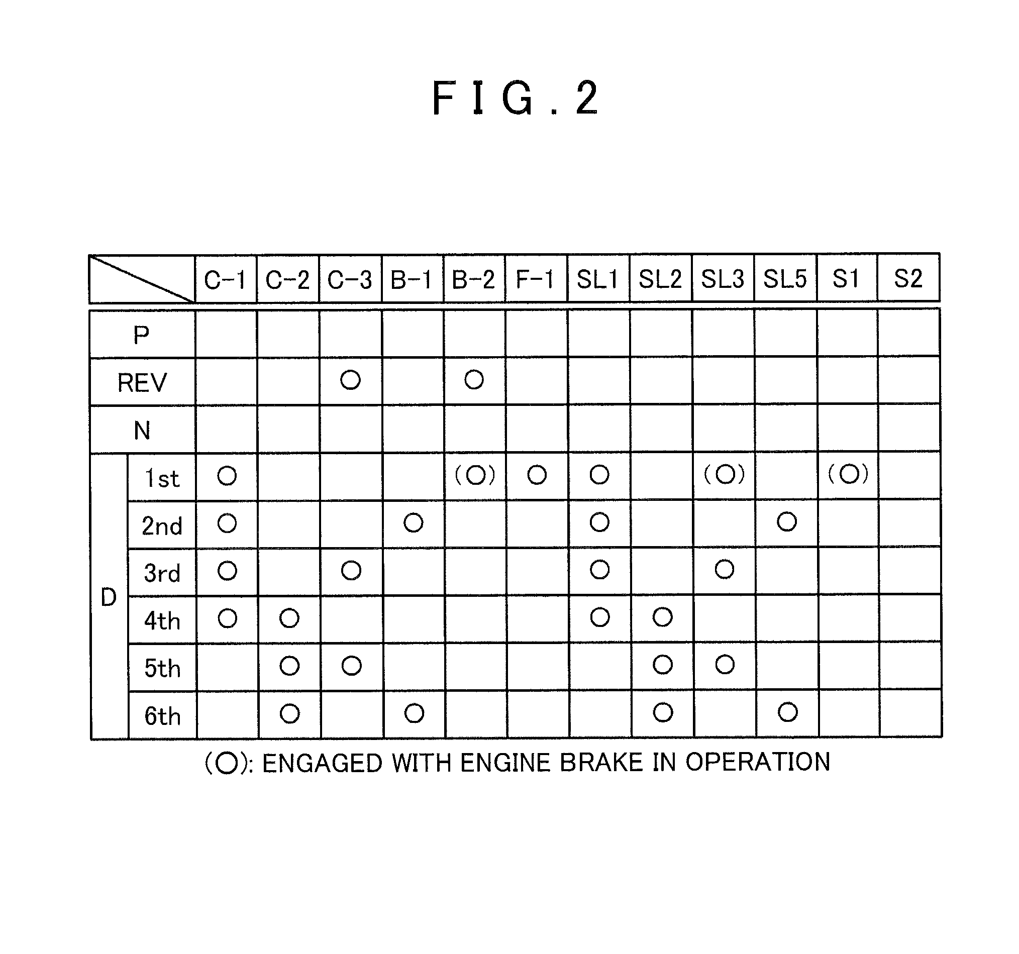
[0030]FIG. 1 is a diagram illustrating a schematic configuration of an automobile 10. FIG. 2 is an operation table of a speed change mechanism 40.

[0031]As illustrated in FIG. 1, the automobile 10 includes: an engine 12 which is an internal combustion engine that outputs power generated by explosive combustion of a hydrocarbon fuel such as gasoline and light oil; an engine electronic control unit (engine ECU) 15 that controls operation of the engine 12; an automatic transmission 20 connected to a crankshaft 14 of the engine 12 and to axles 18a and 18b for left and right wheels 19a and 19b, respectively, to transfer power from the engine 12 to the axles 18a and 18b; an automatic transmission electronic control unit (AT ECU) 16 that controls the automatic transmission 20; and a main electronic control unit (main ECU) 90 that controls the entire vehicle. A shift position SP from a shift position sensor 92 that...


PUM


Abstract

A spool valve that has a hollow portion formed with an input port, a first output port, and a second output port, and a spool capable of sliding within the hollow portion and having a plurality of lands, the spool valve being configured to distribute output for input to the input port to the first output port and the second output port in accordance with a proportion of distribution that matches a position of the spool. An opening of the second output port is formed in such a shape that a width of the opening becomes gradually smaller in a direction of movement of the spool in which distribution of the output to the first output port is increased.

Description

TECHNICAL FIELD[0001]The present invention relates to a spool valve that includes a hollow portion formed with an input port, a first output port, and a second output port, and a spool capable of sliding within the hollow portion and having a plurality of lands, the spool valve being configured to distribute input to the input port to the first output port and the second output port in accordance with a proportion of distribution that matches the position of the spool, and to a lubricating oil supply device that uses the spool valve.BACKGROUND ART[0002]Hitherto, there has been proposed a spool valve of this type, including a spool having a large-diameter land portion and a small-diameter land portion, and a housing that houses the spool so as to be movable in the axial direction (see Patent Document 1, for example). In the spool valve, a liquid chamber is defined by respective facing surfaces of the large-diameter land portion and the small-diameter land portion of the spool and the...

Claims


Application Information

Patent Timeline
Patent Type & Authority Patents(United States)
IPC IPC(8): F16D31/02F16H57/04F16K11/07F16H63/30F16H61/02F16H3/66
CPCF16H57/0435F16H57/0446F16H57/0484F16H61/0276F16H63/3023F16K11/0716F16H3/663F16H2061/0279F16H2200/0052F16H2200/2007F16H2200/2023F16H2200/2043F16H2200/2066F16H2200/2082Y10T137/8671F16H57/0434F16K11/07
Inventor KUTSUBO, HIROYUKIKOJIMA, KAZUKISHIMIZU, TETSUYATSUCHIDA, KENICHIISHIKAWA, KAZUNORIISHIKAWA, TOMOMI
Owner AISIN AW CO LTD
Why Eureka
Try Eureka