Mechanical seal

a mechanical seal and sealing technology, applied in the direction of engine seals, engine components, mechanical apparatus, etc., can solve the problems of sliding pairs having relatively bad dry run properties, not very resistant materials to abrasion attacks,

Active Publication Date: 2017-02-14
KACO
View PDF9 Cites 0 Cited by
  • Summary
  • Abstract
  • Description
  • Claims
  • Application Information

AI Technical Summary

Benefits of technology

[0005]The mechanical seal according to the invention is characterized in that the inlet conduit is positioned between the radial housing bottom and the radial ring segment of the sleeve to which the counter ring is fixedly connected. The sleeve of the mechanical seal is fixedly connected with the shaft to be sealed, for example, is pressed onto it. Because the inlet conduit is limited by components of the mechanical seal, the inlet conduit can be provided in a very simple way and in accordance with respective specifications for the mechanical seal. In particular, the height of the inlet conduit can be very simply adjusted. It is thereby possible to embody the inlet conduit, for example, in a range of from 0.5 mm up to 4 mm in respect to height. The housing bottom and the ring segment of the sleeve are mutually adjusted during assembly of the mechanical seal which is possible in an easy and inexpensive manner.
[0008]The inlet conduit is advantageously an annular gap which is provided between the radial housing bottom and the radial ring segment of the sleeve. The collecting space of the mechanical seal can thereby be filled simply and quickly with coolant / lubrication medium.
[0009]A simply easy embodiment results when the inlet conduit extends straight across its radial length. The coolant / lubricant can then be easily guided into the collecting space.
[0013]So that the medium can be retained for a long time in the collecting space of the mechanical seal, the ratio of the radial distance of the external cylindrical wall of the sleeve from the edge of the central opening in the housing bottom to the radial distance of the edge of the central opening in the housing bottom to the internal cylindrical wall of the sleeve is in a range from about 1.5:1 to about 3:1. A large radial length of the supply conduit is achieved as a result of this distance ratio and this ensures a long residence time of the medium in the collecting space in case of dry run operation. On the one hand, the medium in the collecting space is evenly distributed by the rotary counter ring in the collecting space and, on the other hand, and is caused to rotate. On account of the distance ratio it is guaranteed in spite of the flow of the medium in the collecting space that the medium remains long enough in the collecting space and cools and lubricates the sliding partners sufficiently.
[0017]In an advantageous embodiment, this cover is an extended segment (extension) of a spring plate on which a compression spring that axially loads the slide ring is supported. It is therefore not necessary to provide a separate component as a cover which would have to be produced and mounted in the mechanical seal as an additional part.
[0018]In an advantageous embodiment, the bottom of the housing and / or the ring segment of the sleeve can be provided with structures and / or geometries that are rotation-independent or rotation-dependent. A ventilation of the annular gap can be obtained thereby. Moreover, escape of the coolant / lubricant from the collecting space is thereby made more difficult. The structures or geometries provide in this case that the medium is returned in the direction of the collecting space.

Problems solved by technology

However, such materials are not very resistant toward abrasive attack.
Such sliding pairs however have relatively bad dry run properties.

Method used


Image

  • Mechanical seal
  • Mechanical seal
  • Mechanical seal

Examples


Embodiment Construction

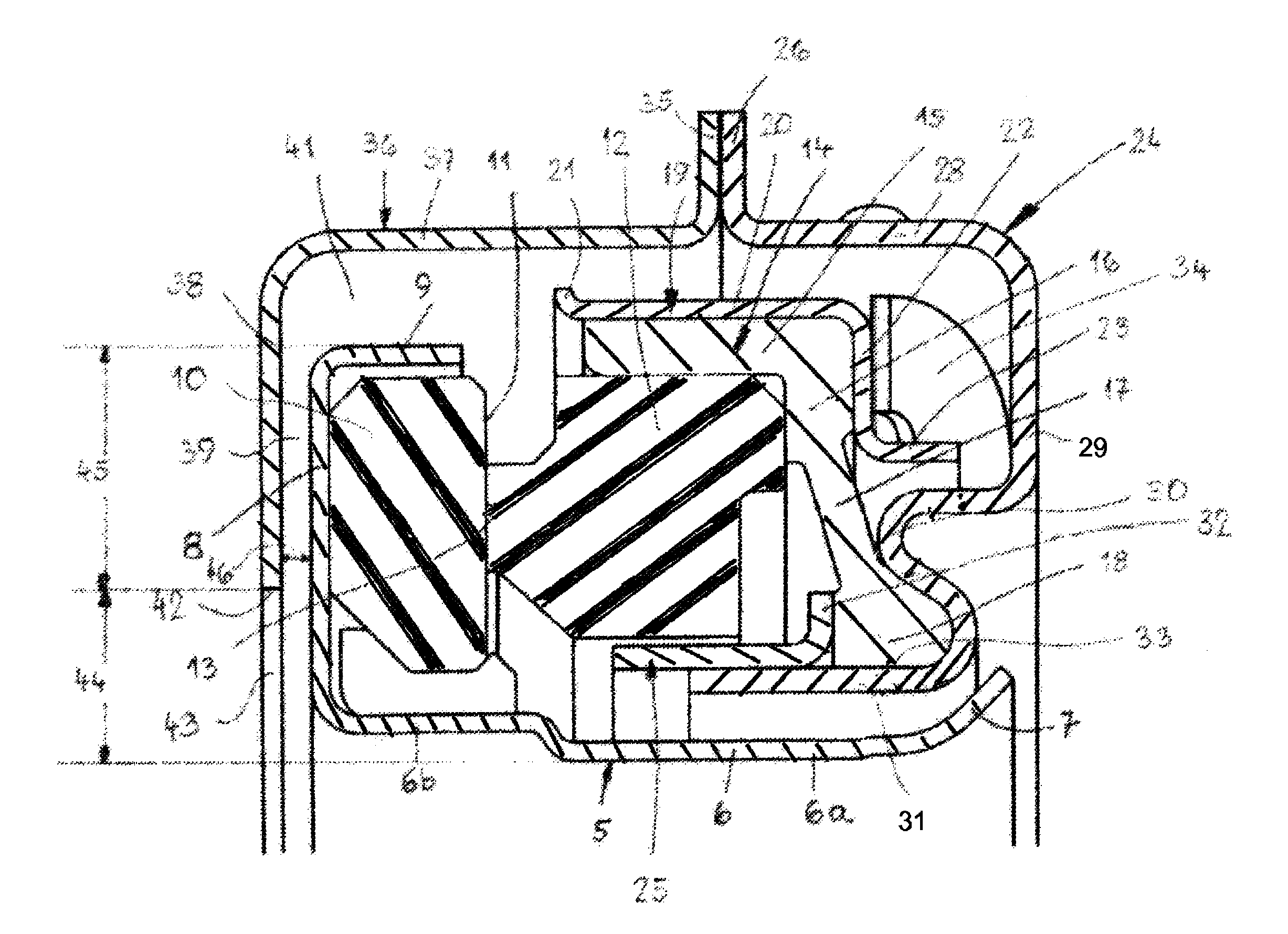
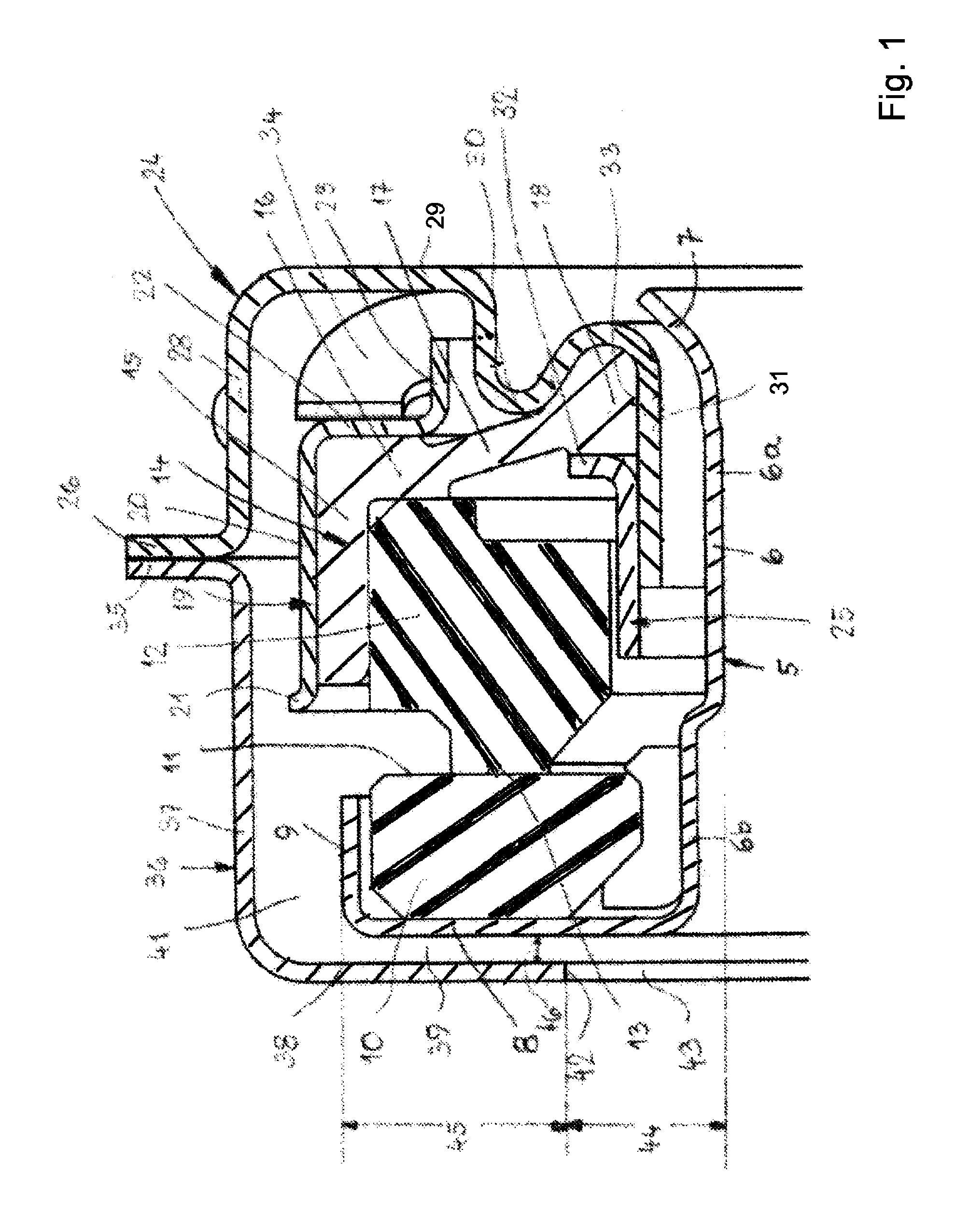
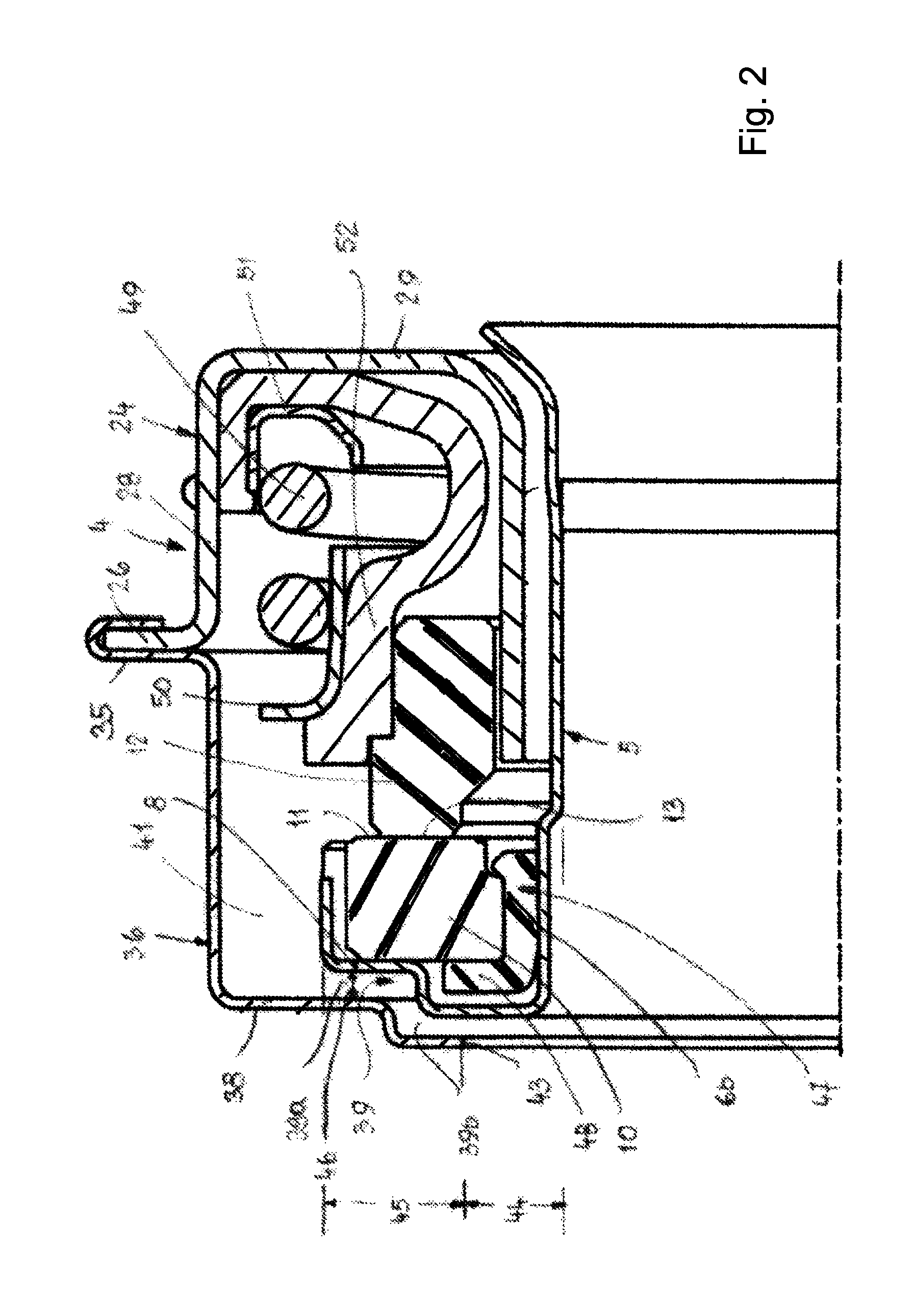
[0025]The shaft seals described in the following are used in particular in water pumps of automobiles. In FIG. 4, such a water pump is shown in an exemplary embodiment; it has a housing 1 in which a pump shaft 2 is supported in a known manner so as to be rotatable. A pump wheel 3 is supported on the end of the pump shaft 2 projecting from the housing 1. The pump shaft 2 is sealed by a shaft seal 4 which is installed in the housing 1. The shaft seal 4 is a mechanical seal. With the aid of FIGS. 1 to 3, different embodiments of such a mechanical seal will be described in more detail; these mechanical seals are embodied such that dry running of the sliding pair is prevented.

[0026]The mechanical seal according to FIG. 1 has a sleeve 5 with which the mechanical seal is seated on the pump shaft 2. The sleeve 5 has a wall 6 which is comprised across its axial length of two wall segments 6a and 6b that are radially displaced relative to each other. With the wall segment 6a the sleeve 5 is s...


PUM


Abstract

A mechanical seal has a housing having a collecting space for a coolant / lubricant medium. A sleeve is disposed in the housing. A counter ring is disposed in the housing and fixedly connected to the sleeve. A slide ring is disposed in the housing and interacts with the counter ring. At least one inlet conduit communicating with the collecting space is provided. The at least one inlet conduit is positioned between a radial bottom of the housing and a radial ring segment of the sleeve.

Description

BACKGROUND OF THE INVENTION[0001]The invention concerns a mechanical seal comprising a counter ring and a slide ring arranged in a housing in which a collecting space for a coolant / lubricant is provided into which at least one inlet conduit line opens.[0002]Mechanical seals are used, for example, in water pumps of automobiles. The mechanical seal must be embodied in such a way that it can be operated without the liquid to be sealed for a sufficiently long period. The heat generated in the sealing gap between counter ring and slide ring should not cause thermal damage of the sliding partners themselves nor should it cause thermal damage of the sealing components surrounding the sliding partners. So that in dry run conditions a sufficiently low sealing gap temperature is reached, special coal graphite materials which are relatively soft are used for the slide ring. However, such materials are not very resistant toward abrasive attack. The counter ring is typically made of a hard mater...

Claims


Application Information

Patent Timeline
Patent Type & Authority Patents(United States)
IPC IPC(8): F16J15/00F16J15/16F16J15/34
CPCF16J15/348F16J15/16
Inventor SAUTER, BERNDHOFFMANN, TOBIAS
Owner KACO
Why Eureka
Try Eureka