Spectroscopic assembly and method

a technology of optical spectrometers and assemblies, applied in the field of spectroscopic instruments and methods, can solve the problems of reducing the size of the spectrometer assembly, affecting the miniaturization of the spectrometer, and being relatively bulky, so as to reduce the angular dependence of the transmission wavelength and the size of the optical spectrometer

Active Publication Date: 2017-02-14
VIAVI SOLUTIONS INC
View PDF41 Cites 8 Cited by
  • Summary
  • Abstract
  • Description
  • Claims
  • Application Information

AI Technical Summary

Benefits of technology

[0008]One factor that impedes miniaturization of spectrometers is necessity to collimate optical beams to ensure sufficient wavelength selectivity of optical filters used in the spectrometers. To collimate optical beams, lenses or concave mirrors are required. These elements are relatively bulky, and require free-space propagation for at least one focal length, which increases the size of the spectrometer assembly.
[0009]In accordance with the invention, a spectrometer assembly includes an optical filter that can preserve a suitable wavelength selectivity even in a highly converging or diverging optical beam, thereby alleviating the need for collimating optical elements and reducing size. A filter for such a spectrometer assembly includes a stack of continuous, non-micro-structured alternating dielectric and metal layers, which results in lessening of angular sensitivity of the transmission wavelength.
[0015]wherein the first signal filter includes continuous, non-micro-structured metal and dielectric layers stacked in alternation, whereby angular sensitivity of the first signal transmission wavelength is lessened.
[0023]In accordance with another aspect of the invention, there is further provided a use of a transmission optical filter in an optical spectrometer, the transmission optical filter including continuous, non-micro-structured metal and dielectric layers stacked in alternation, to discriminate between excitation and signal wavelengths, wherein the presence of the continuous, non-patterned metal layers in the optical filter lessens angular dependence of a transmission wavelength of the optical filter, thereby lessening a size of the optical spectrometer.

Problems solved by technology

One factor that impedes miniaturization of spectrometers is necessity to collimate optical beams to ensure sufficient wavelength selectivity of optical filters used in the spectrometers.
These elements are relatively bulky, and require free-space propagation for at least one focal length, which increases the size of the spectrometer assembly.
A filter for such a spectrometer assembly includes a stack of continuous, non-micro-structured alternating dielectric and metal layers, which results in lessening of angular sensitivity of the transmission wavelength.

Method used


Image

  • Spectroscopic assembly and method
  • Spectroscopic assembly and method
  • Spectroscopic assembly and method

Examples


Embodiment Construction

[0040]While the present teachings are described in conjunction with various embodiments and examples, it is not intended that the present teachings be limited to such embodiments. On the contrary, the present teachings encompass various alternatives and equivalents, as will be appreciated by those of skill in the art.

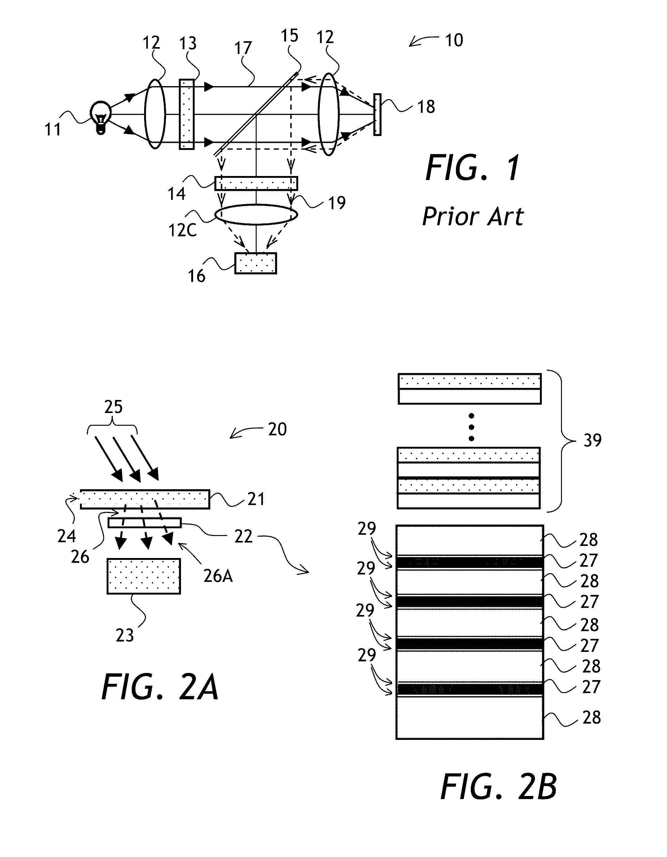
[0041]Referring to FIG. 2A and FIG. 3, a spectrometer assembly 20 of FIG. 2A includes a sample holder 21, an optical filter 22 (or “signal filter 22”) optically coupled to the sample holder 21, and a photodetector 23 optically coupled to the signal filter 22. The sample holder 21 holds a sample 24, for example a fluid having a fluorescent dye or protein dissolved therein. The sample holder 21, the signal filter 22, and the photodetector 23 can be held together by a housing, not shown, or simply attached together into a stack. In operation, the sample 24 is excited with excitation light 25 having a spectrum 35 of FIG. 3, preferably matching an absorption or excitation sp...


PUM

PropertyMeasurementUnit
total thicknessaaaaaaaaaa
collection angleaaaaaaaaaa

Abstract

A spectrometer assembly is provided having an optical transmission filter including a stack of continuous, non-patterned alternating dielectric and metal layers. Angle-dependent transmission wavelength shift of the optical transmission filter with continuous metal layers is small e.g. in comparison with multilayer dielectric filters, facilitating size reduction of the spectrometer assembly.

Description

CROSS-REFERENCE TO RELATED APPLICATIONS[0001]This application is a continuation-in-part of U.S. patent application No. 13 / 720,728 filed Dec. 19, 2012, which is incorporated herein by reference.TECHNICAL FIELD[0002]The present invention relates to spectroscopic instrumentation and methods, and in particular to spectroscopic instrumentation and methods employing optical filters.BACKGROUND OF THE INVENTION[0003]Transmission optical filters are used in spectroscopic applications to select a wavelength or a band of wavelengths of light emitted by a sample, and / or to select a wavelength or a band of wavelengths of light illuminating the sample. For example, in a fluorescence spectroscopic application, a beam of excitation light illuminates a sample, and light at a longer wavelength is detected to obtain its optical spectrum and / or to determine a total level of fluorescence emitted by the sample in response to excitation by the excitation light.[0004]A single bandpass transmission optical ...

Claims


Application Information

Patent Timeline
Patent Type & Authority Patents(United States)
IPC IPC(8): G02B5/08G01J3/02G01N21/64G01J3/44G02B5/28G02B5/20F21V9/04F21V9/06G01J3/12
CPCG01J3/0229G01J3/0256G01J3/4406G01N21/645G02B5/285G01J2003/1226A61B5/0059A61B5/0071A61B5/0075A61B5/14532A61B5/1455A61B5/1459A61B2562/0233A61B2562/12G01N21/6428G01N2021/6439G01N2021/6471G01J1/0488G01J1/42
Inventor OCKENFUSS, GEORG J.
Owner VIAVI SOLUTIONS INC
Why Eureka
Try Eureka