Organic light emitting display device and method of manufacturing the same

a technology of light-emitting display device and organic light-emitting element, which is applied in the direction of basic electric elements, semiconductor devices, electrical apparatus, etc., can solve the problems of non-uniform achieve uniform luminance of organic light-emitting display device, improve life reliability of organic light-emitting element, and reduce voltage drop in cathode

Active Publication Date: 2017-02-14
LG DISPLAY CO LTD
View PDF10 Cites 13 Cited by
  • Summary
  • Abstract
  • Description
  • Claims
  • Application Information

AI Technical Summary

Benefits of technology

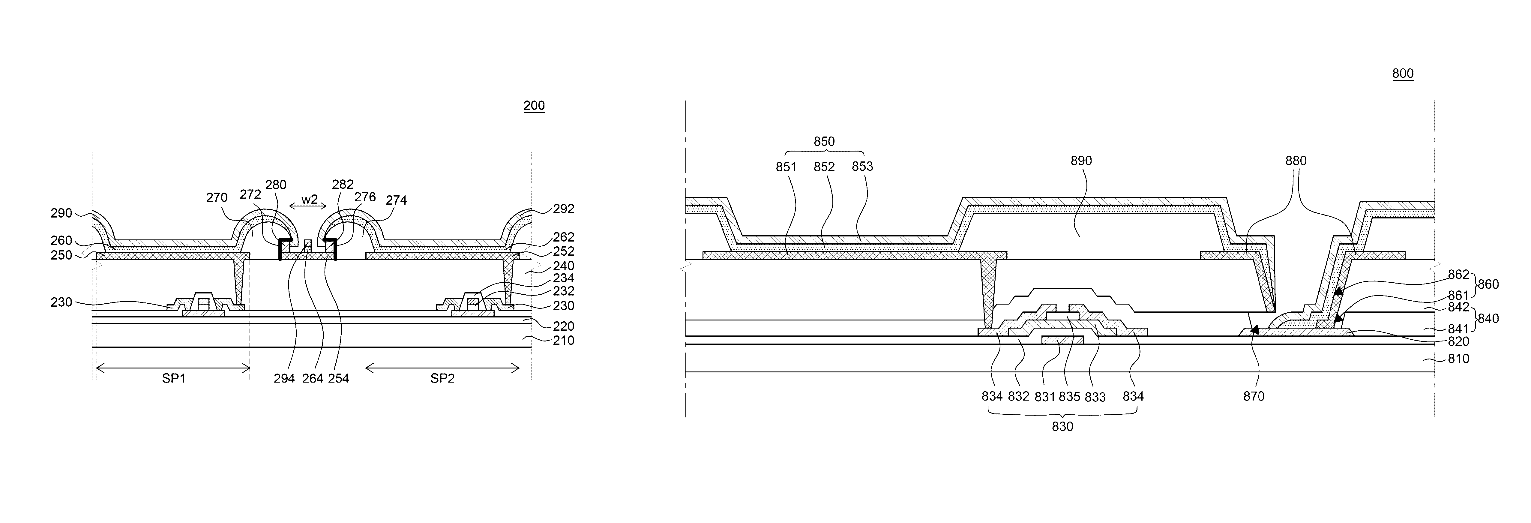
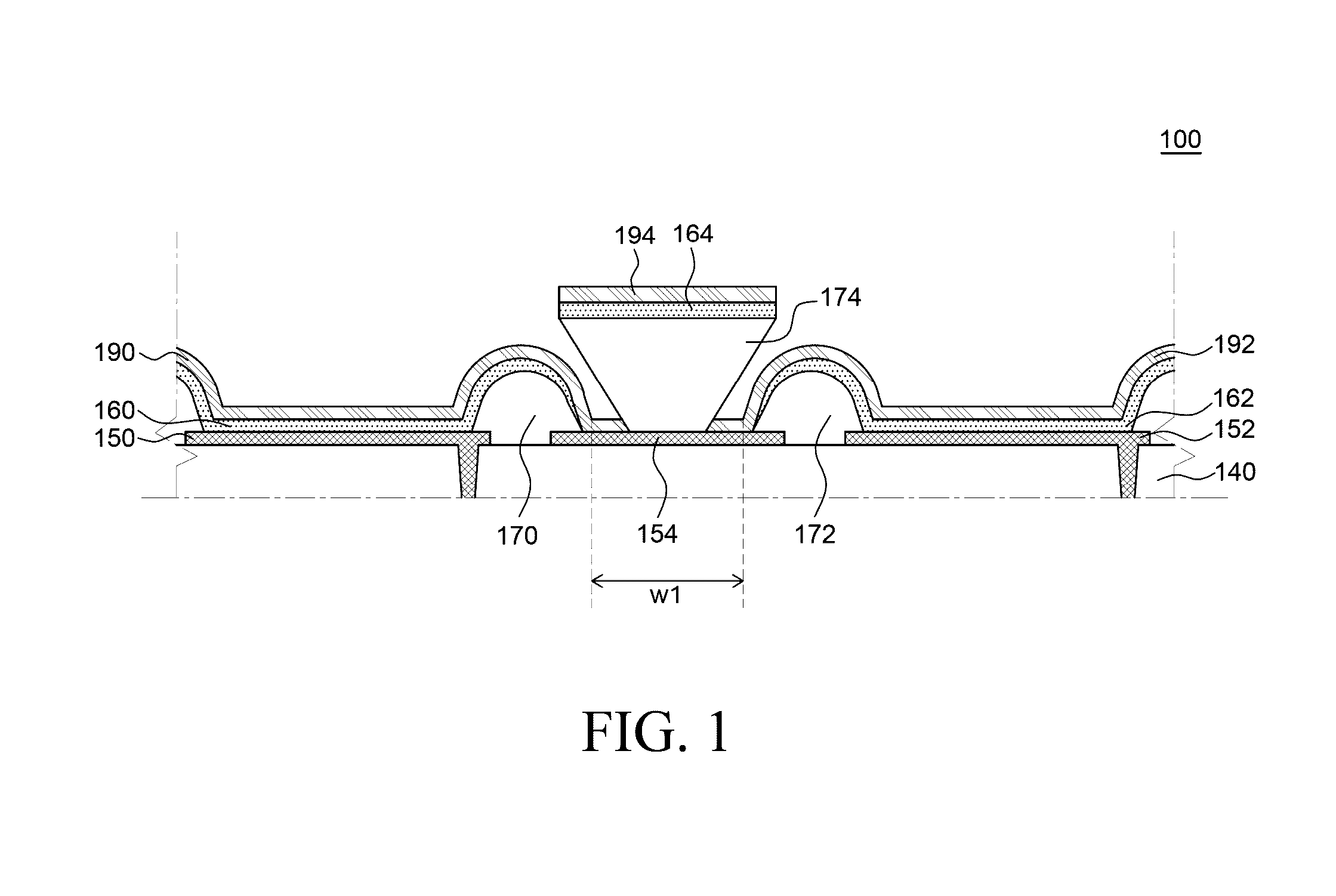
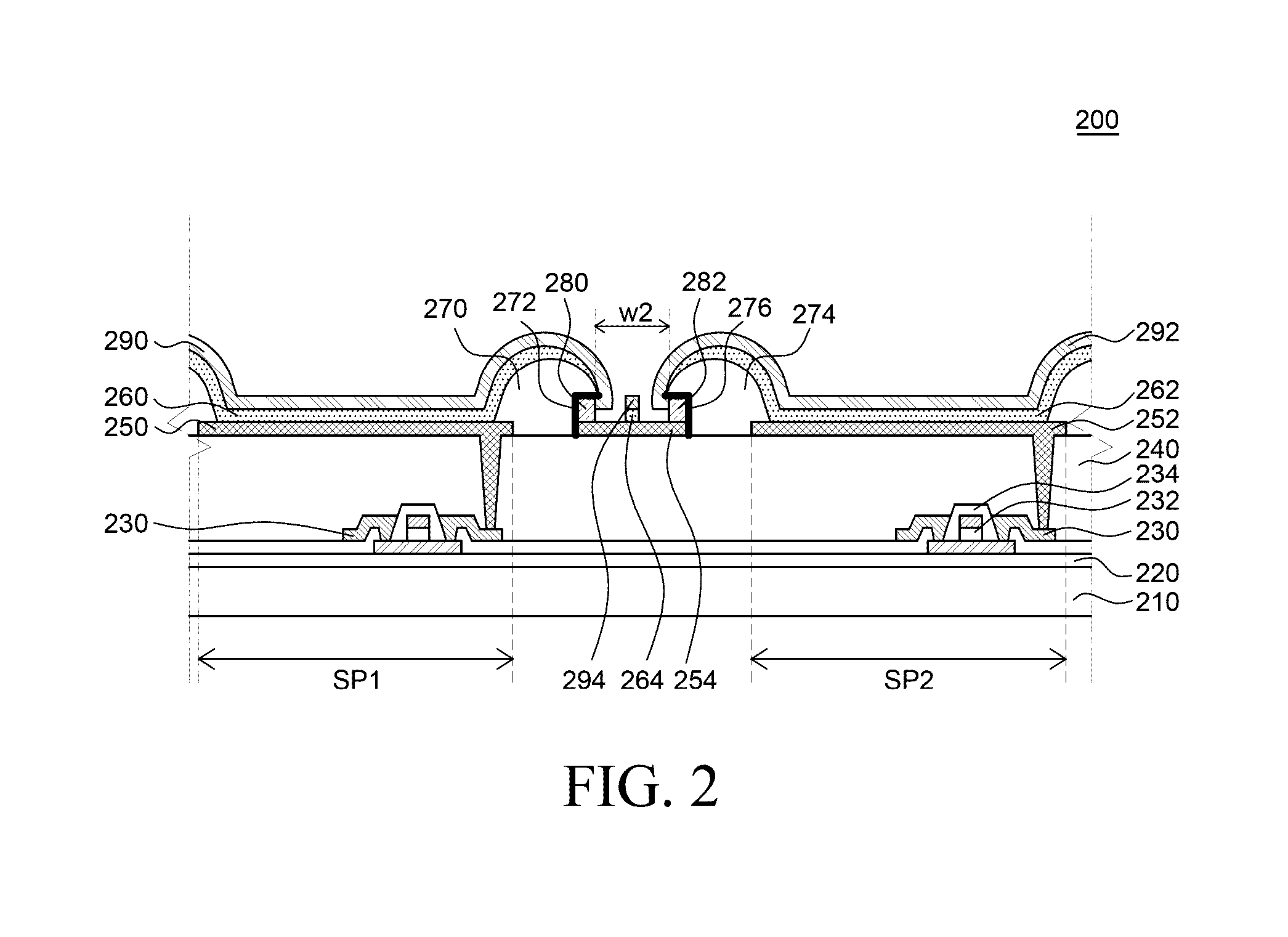
[0014]The inventors of the present disclosure recognized the problems occurring when manufacturing an organic light emitting display device of the related art including an auxiliary electrode as described above. They invented an organic light emitting display device having a new structure which is capable of suppressing a voltage drop in a cathode and also minimizing a decrease in an opening ratio of the organic light emitting display device.
[0015]An object to be achieved by the present disclosure is to provide an organic light emitting display device and a method of manufacturing the same, which is capable of minimizing a voltage drop caused by a cathode in order to maintain uniformity in luminance of the entire display.
[0016]Another object to be achieved by the present disclosure is to provide an organic light emitting display device and a method of manufacturing the same that is capable of solving a problem of decrease in an opening ratio caused by disposing an auxiliary electrode between banks.

Problems solved by technology

Thus, in the case of a large-area organic light emitting display device, as a distance from a voltage supply pad unit is increased, a voltage drop is further increased, which may cause a problem in non-uniformity in luminance of the organic light emitting display device.

Method used


Image

  • Organic light emitting display device and method of manufacturing the same
  • Organic light emitting display device and method of manufacturing the same
  • Organic light emitting display device and method of manufacturing the same

Examples


Embodiment Construction

[0041]Advantages and features of the present disclosure, and methods for accomplishing the same will be more clearly understood from exemplary embodiments described below with reference to the accompanying drawings. However, the present disclosure is not limited to the following exemplary embodiments but may be implemented in various different forms. The exemplary embodiments are provided only to complete disclosure of the present disclosure and to fully provide a person having ordinary skill in the art to which the present disclosure pertains with the category of the disclosure, and the present disclosure will be defined by the appended claims.

[0042]The shapes, sizes, ratios, angles, numbers, and the like illustrated in the accompanying drawings for describing the exemplary embodiments of the present disclosure are merely examples, and the present disclosure is not limited thereto. Like reference numerals generally denote like elements throughout the present specification. Further,...


PUM


Abstract

Provided is an organic light emitting display device including: a substrate; a first anode and a second anode formed on the substrate; a first auxiliary electrode formed between the first anode and the second anode; a first organic light emitting layer and a second organic light emitting layer; a first bank including an undercut formed on an upper part of a first edge of the first auxiliary electrode; a second bank including an undercut formed on an upper part of a second edge of the first auxiliary electrode; a second auxiliary electrode disposed between the undercut of the first bank and the first auxiliary electrode; a third auxiliary electrode disposed between the undercut of the second bank and the first auxiliary electrode; a first cathode electrically connected with the second auxiliary electrode; and a second cathode electrically connected with the third auxiliary electrode.

Description

CROSS-REFERENCE TO RELATED APPLICATIONS[0001]This application claims the priority of Patent Application No. 10-2014-0100273 filed on Aug. 5, 2014 and Patent Application No. 10-2015-0058894 filed on Apr. 27, 2015, in the Korean Intellectual Property Office. The disclosures of all these applications are incorporated herein by reference.BACKGROUND OF THE INVENTION[0002]Field of the Invention[0003]The present disclosure relates to an organic light emitting display device and a method of manufacturing the same, and more particularly, to an organic light emitting display device and a method of manufacturing the organic light emitting display device capable of minimizing a voltage drop in a cathode and also securing a high opening ratio.[0004]Description of the Related Art[0005]An organic light emitting display device (OLED) is a self-light emitting display device that does not need a separate light source unlike a liquid crystal display device. Thus, the organic light emitting display dev...

Claims


Application Information

Patent Timeline
Patent Type & Authority Patents(United States)
IPC IPC(8): H01L27/12H01L51/52H01L27/32
CPCH01L27/1225H01L27/3246H01L27/3279H01L51/5228H01L51/5234H01L2227/323H10K59/122H10K59/1315H10K59/1201H10K59/80524H10K59/80522H10K50/824H10K50/828
Inventor HEO, JOONYOUNGPANG, HEESUK
Owner LG DISPLAY CO LTD
Why Eureka
Try Eureka