Touch panel

a technology of touch panel and input device, which is applied in the direction of electrical/magnetic measuring arrangement, instruments, computing, etc., can solve the problem that the input device is difficult to be formed thin, and achieve the effect of preventing electromagnetic noise, reducing light transmittance at this portion, and easy patterning

Active Publication Date: 2017-02-21
MURATA MFG CO LTD
View PDF18 Cites 11 Cited by
  • Summary
  • Abstract
  • Description
  • Claims
  • Application Information

AI Technical Summary

Benefits of technology

[0006]Accordingly, an object of the present invention is to provide a touch panel that can detect a touch position and a pressing amount, and can be formed to be thin.
[0021]According to the present invention, a touch panel that can detect a touch position and a pressing amount and can be formed to be thin can be implemented.

Problems solved by technology

Therefore, the thickness of the touch input device becomes equal to or more than the total of the thickness of the touch panel and the thickness of the pressure sensor, and hence, the touch input device is difficult to be formed to be thin.

Method used


Image

  • Touch panel
  • Touch panel
  • Touch panel

Examples


Embodiment Construction

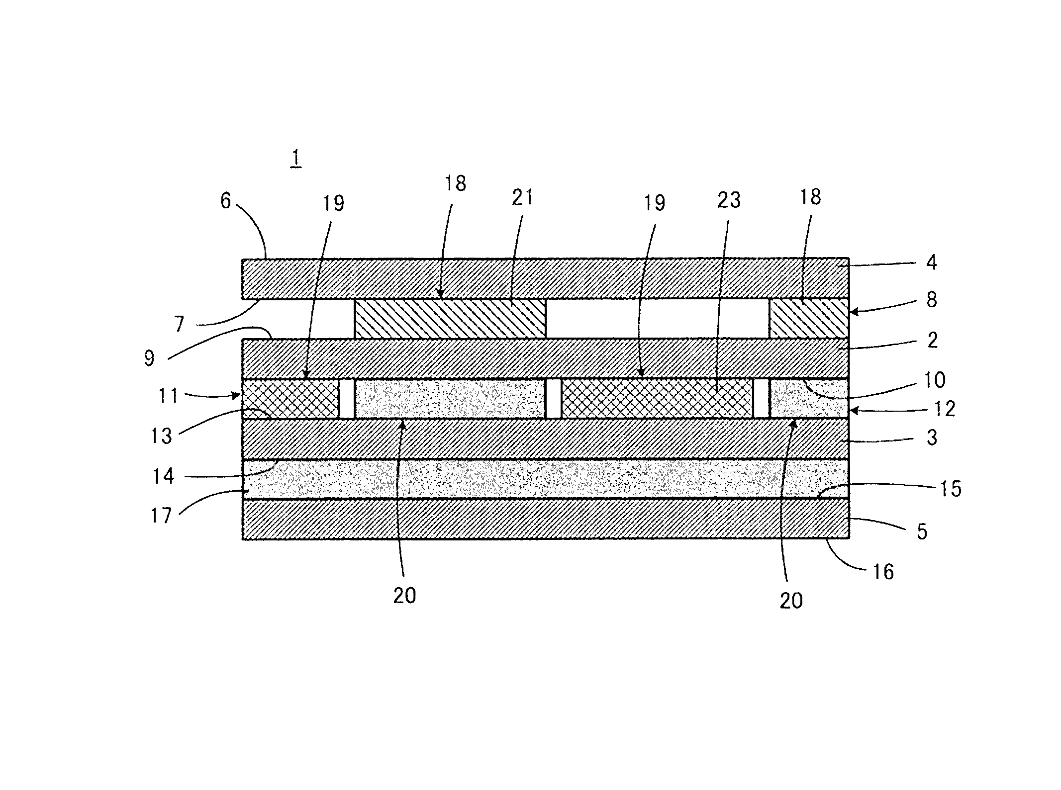
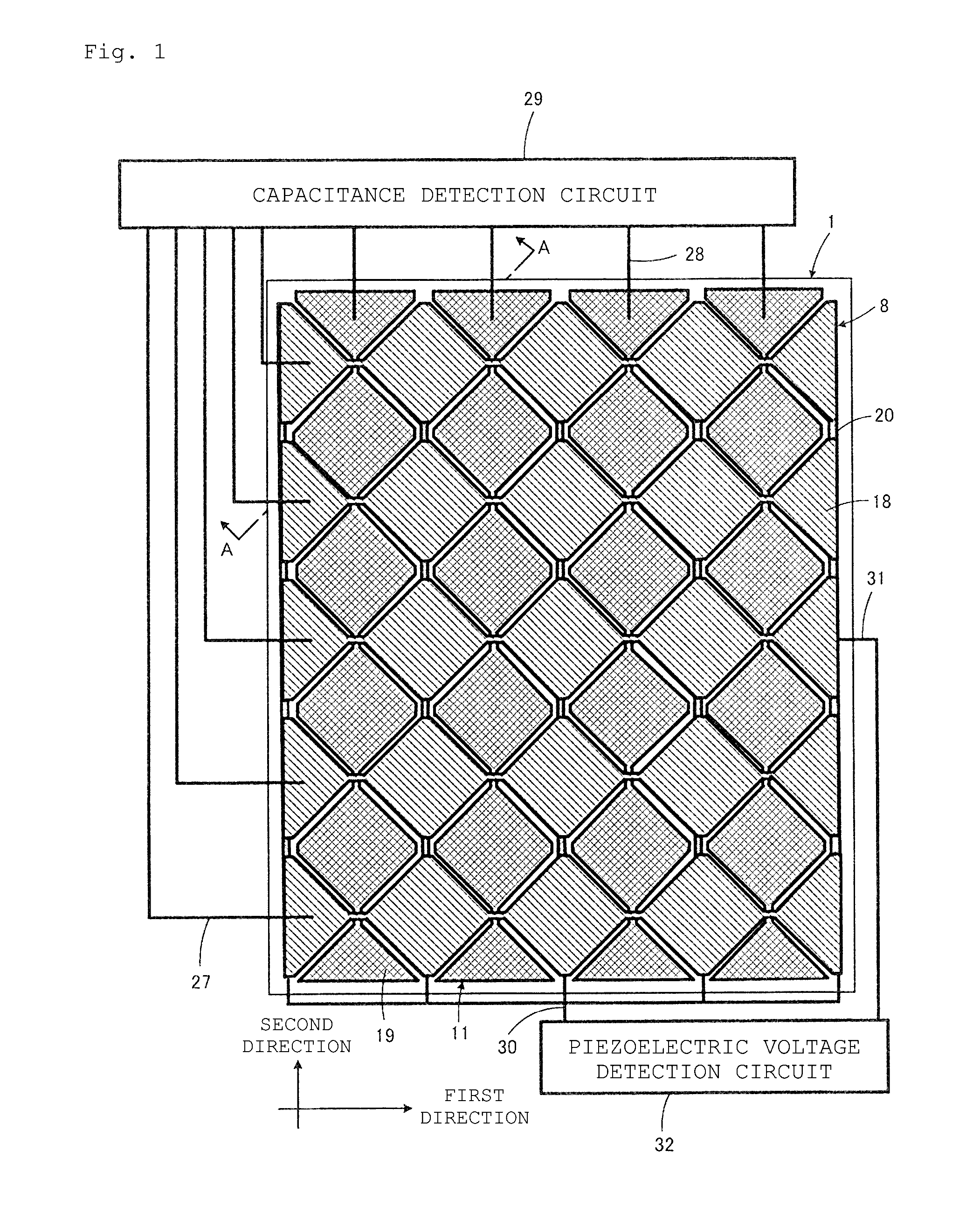
[0033]A touch panel 1 according to one embodiment of the present invention will be described with reference to FIGS. 1 to 5.

[0034]As well illustrated in FIG. 5, the touch panel 1 includes at least a dielectric film 2 and a piezoelectric film 3. In this embodiment, the touch panel 1 also includes an upper protection film 4 and a lower protection film 5. The upper protection film 4, the dielectric film 2, the piezoelectric film 3, and the lower protection film 5 are stacked in this order from top in the touch panel 1.

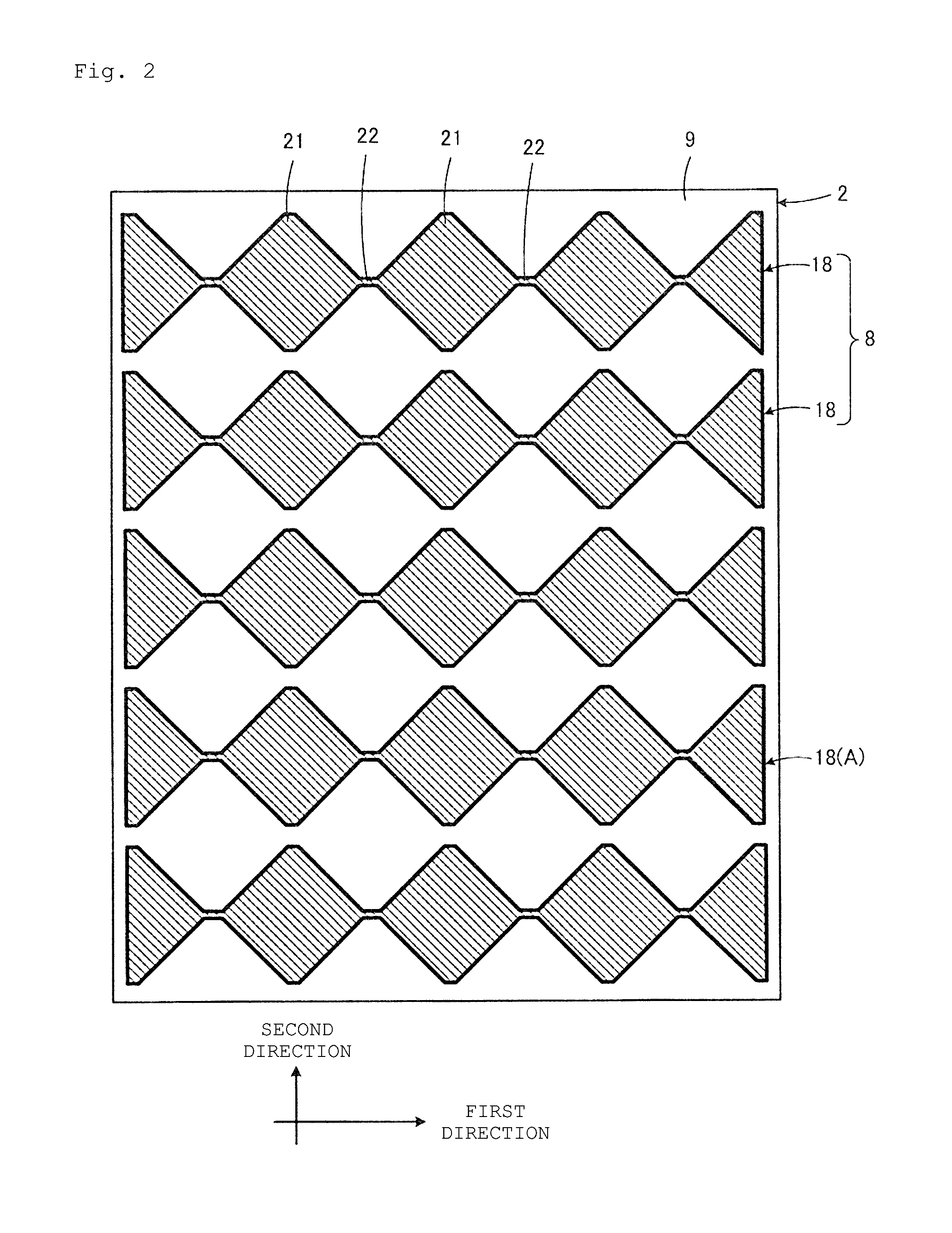
[0035]An upper main surface 6 of the upper protection film 4 becomes an operation surface touched with operator's fingers or the like. A first capacitance detection electrode 8 is formed on a lower main surface 7 of the upper protection film 4 with a pattern as illustrated in FIG. 2.

[0036]An upper main surface 9 of the dielectric film 2 is opposite to the lower main surface 7 of the upper protection film 4 via the first capacitance detection electrode 8. A second capacita...


PUM


Abstract

A touch panel that includes a dielectric film and a piezoelectric film. A first capacitance detection electrode is disposed on an upper main surface of the dielectric film, a second capacitance detection electrode and a first piezoelectric voltage detection electrode are disposed between a lower main surface of the dielectric film and an upper main surface of the piezoelectric film, and a second piezoelectric voltage detection electrode is disposed on a lower main surface of the piezoelectric film. The first capacitance detection electrode includes plural sub-electrodes extending in a first direction, the second capacitance detection electrode includes plural sub-electrodes extending in a second direction orthogonal to the first direction, and the first piezoelectric voltage detection electrode includes plural sub-electrodes disposed between the plural sub-electrodes.

Description

CROSS REFERENCE TO RELATED APPLICATIONS[0001]The present application is a continuation of International application No. PCT / JP2013 / 073467, filed Sep. 2, 2013, which claims priority to Japanese Patent Application No. 2012-206407, filed Sep. 20, 2012, the entire contents of each of which are incorporated herein by reference.FIELD OF THE INVENTION[0002]The present invention relates to a touch panel that can detect a position pressed by fingers or the like and a pressing amount upon the pressing operation.BACKGROUND OF THE INVENTION[0003]Various types of touch panels that simultaneously detect a touch position when an operator touches a planar operation surface with his / her finger or the like and a pressing amount upon the touch have conventionally been proposed. For example, Japanese Unexamined Patent Publication No. 05-61592 (Patent Document 1) describes a touch input device having a structure in which a flat-plate pressure sensor and a touch panel detecting a touch position are super...

Claims


Application Information

Patent Timeline
Patent Type & Authority Patents(United States)
IPC IPC(8): G06F3/044G01B7/00
CPCG06F3/044G01B7/003G01B2210/58G06F2203/04105G06F3/0445G06F3/0446G06F3/0448
Inventor ANDO, MASAMICHIINOUE, TAKAFUMI
Owner MURATA MFG CO LTD
Why Eureka
Try Eureka