Suspension board with circuit
a suspension board and circuit technology, applied in the direction of inspection/indication of circuits, integrated arm assemblies, maintaining head carrier alignment, etc., can solve the problems of reduced working efficiency of electrical conduction tests and disadvantages of work limitation on electrical conduction tests, so as to improve the workability of electrical conduction tests
- Summary
- Abstract
- Description
- Claims
- Application Information
AI Technical Summary
Benefits of technology
Problems solved by technology
Method used
Image
Examples
first embodiment
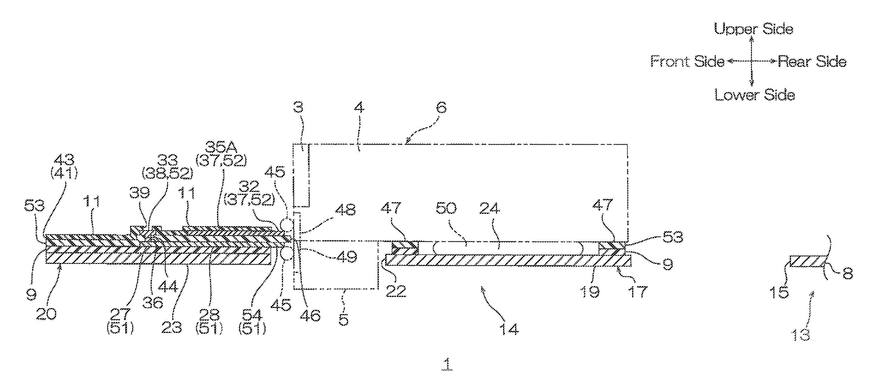
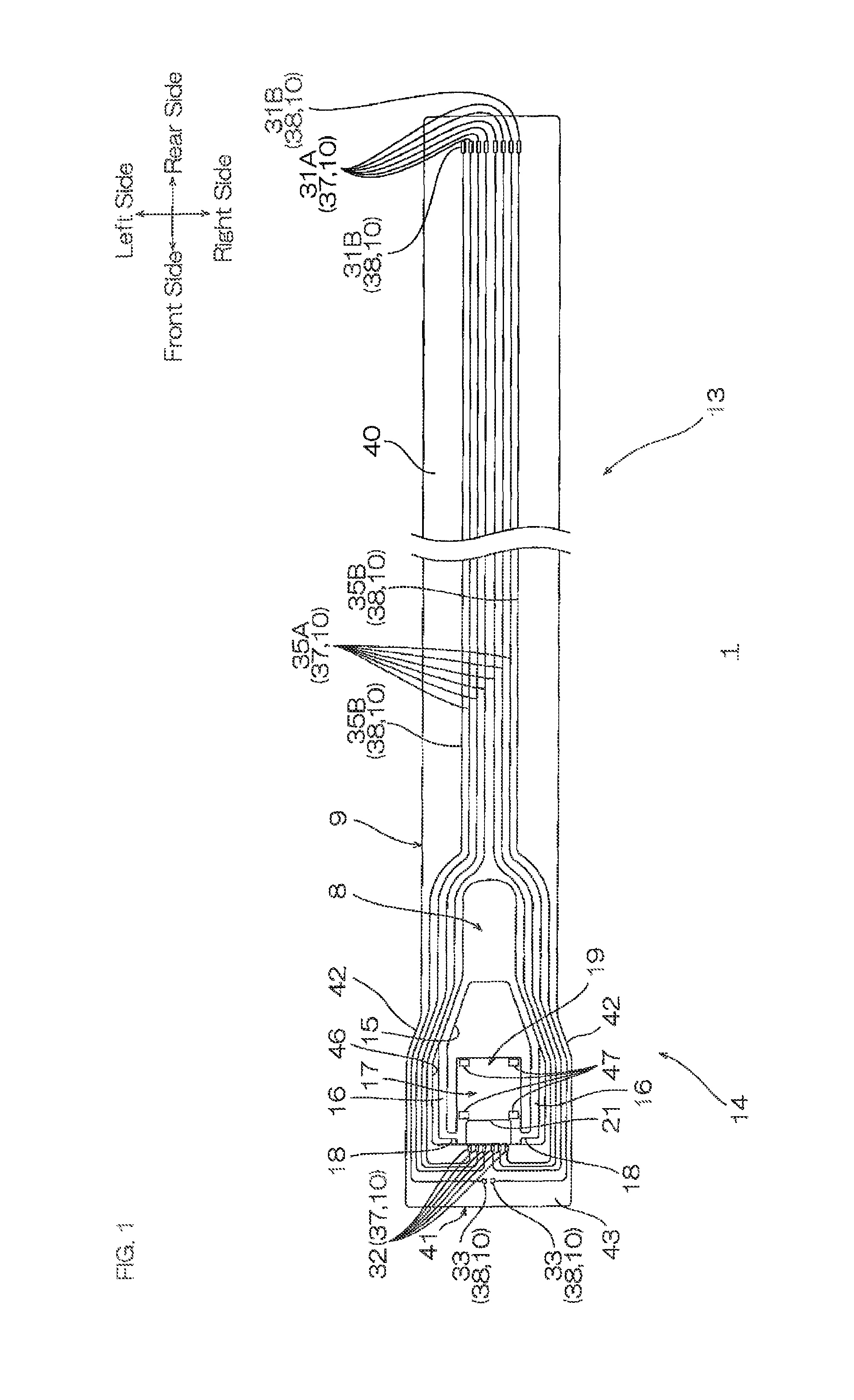
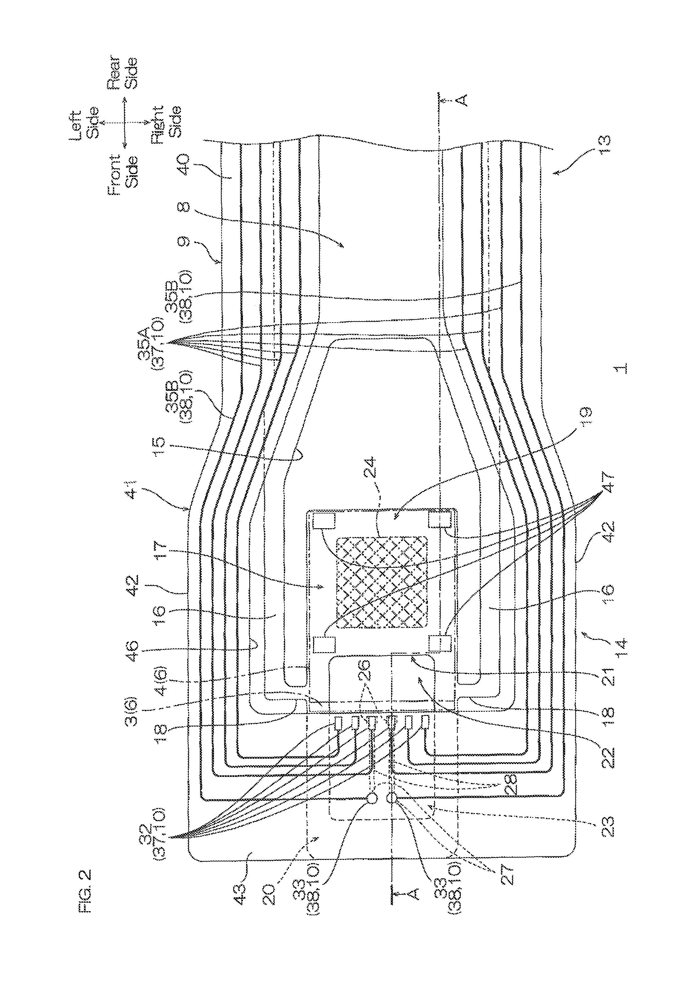
[0049]As shown in FIG. 4, a suspension board with circuit 1 shown in FIG. 1 is mounted with a slider 4 mounted with a magnetic head 3 and a slider unit 6 mounted with a light emitting element 5 as one example of an electronic component to be then mounted on a hard disk drive (not shown).
[0050]As shown in FIG. 1, the suspension board with circuit 1 is formed into a flat belt shape extending in the front-rear direction. As shown in FIG. 5, the suspension board with circuit 1 includes a metal supporting board 8 as one example of a first layer, a base insulating layer 9 that is formed on the metal supporting board 8 as one example of a second layer, a conductive pattern 10 that is formed on the base insulating layer 9 as one example of a third layer, and the cover insulating layer 11 that is formed on the conductive pattern 10 as one example of a fourth layer.
[0051]As shown in FIG. 1, the metal supporting board 8 is formed into a flat belt shape extending in the front-rear direction and...
second embodiment
[0143]The suspension board with circuit 1 of the second embodiment is described with reference to FIG. 7. In the second embodiment, the same reference numerals are provided for members corresponding to each of those described in the above-described first embodiment, and their detailed description is omitted.
[0144]In the above-described first embodiment, as referred to FIG. 5, the metal supporting board 8, the base insulating layer 9, the conductive pattern 10, and the cover insulating layer 11 are included. In the second embodiment, as shown in FIG. 7, the metal supporting board 8, the base insulating layer 9, a first conductive pattern 51 as one example of the first layer, an intermediate insulating layer 53 as one example of the second layer, a second conductive pattern 52 as one example of the third layer, and the cover insulating layer 11 as one example of the fourth layer are included.
[0145]The metal supporting board 8 is formed at the lowermost side of the suspension board wit...
third embodiment
[0158]The suspension board with circuit 1 of the third embodiment is described with reference to FIGS. 8 and 9. In the third embodiment, the same reference numerals are provided for members corresponding to each of those described in the above-described first embodiment, and their detailed description is omitted.
[0159]In the above-described first embodiment, as referred to FIGS. 4 and 5, the connecting terminal opening portions 39 as one example of the second opening portion are, when projected in the thickness direction, formed so as to be included in the conductor-side connecting terminals 33. Alternatively, for example, as shown in FIGS. 8 and 9, metal wire opening portions 55 as one example of the second opening portion can be also, when projected in the thickness direction, formed so as to be overlapped with the metal wires 28.
[0160]The metal wire opening portions 55 pass through the cover insulating layer 11 and the base insulating layer 9 in the thickness direction and expose...
PUM
| Property | Measurement | Unit |
|---|---|---|
| thickness | aaaaa | aaaaa |
| thickness | aaaaa | aaaaa |
| thickness | aaaaa | aaaaa |
Abstract
Description
Claims
Application Information
 - R&D
- Intellectual Property
- Life Sciences
- Materials
- Tech Scout
- Unparalleled Data Quality
- Higher Quality Content
- 60% Fewer Hallucinations
Browse by: Latest US Patents, China's latest patents, Technical Efficacy Thesaurus, Application Domain, Technology Topic, Popular Technical Reports.
© 2025 PatSnap. All rights reserved.Legal|Privacy policy|Modern Slavery Act Transparency Statement|Sitemap|About US| Contact US: help@patsnap.com


