
Microscope connecting unit and microscope system

a technology of connecting units and microscopes, applied in the field of microscope connecting units and microscope systems, can solve the problems of loss of interoperability with peripheral devices, inability to use three or more devices at the same time, and increase in device size, and achieve the effect of higher frame rates

Active Publication Date: 2014-03-04
EVIDENT CORP
View PDF33 Cites 0 Cited by
  • Summary
  • Abstract
  • Description
  • Claims
  • Application Information

AI Technical Summary

Benefits of technology

The invention allows for the microscope to be connected to multiple devices simultaneously without increasing its size or reducing its efficiency. These devices can include irradiating units and detecting units, which can be used simultaneously by combining light paths. This means that the microscope can observe a sample after it has been stimulated with light without missing its response. The technical effect of this invention is that it provides a more flexible and efficient way to use multiple devices with a microscope.

Problems solved by technology

However, with the microscope device according to the Publication of Japanese Patent No. 3069911, it is not possible to use three or more devices simultaneously, such as an observation device, a stimulating device, and an image capturing device for capturing an image showing the response of a sample while observing and stimulating the sample.
However, when the focal distance of the image forming lens is extended, the focal distances of a relay lens system of the visual-observation light path and a TV camera adapter (picture lens) of the image-capturing light path become relatively large, resulting in an increase in size of the device.
Furthermore, interoperability with peripheral devices is lost: for example, the magnification factor of the objective lens changes.
Furthermore, when the distance between the objective lens and the image forming lens is extended and branching means is added, the lens diameter inevitably becomes larger.
This results in disadvantages such as an increase in size of the device as a whole, a higher position of the stage, or reduced working efficiency.

Method used


Image

  • Microscope connecting unit and microscope system
  • Microscope connecting unit and microscope system
  • Microscope connecting unit and microscope system

Examples


first embodiment

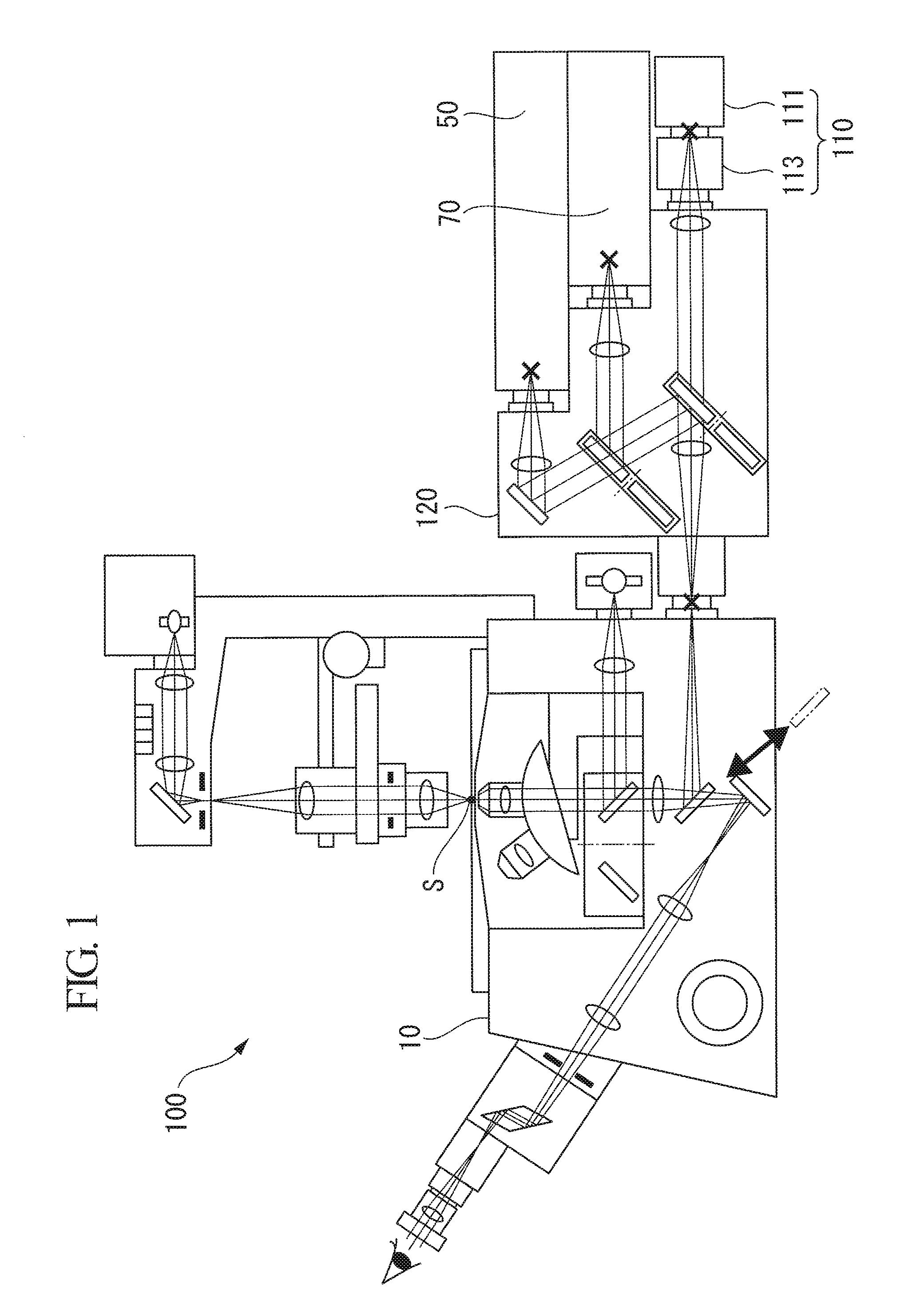
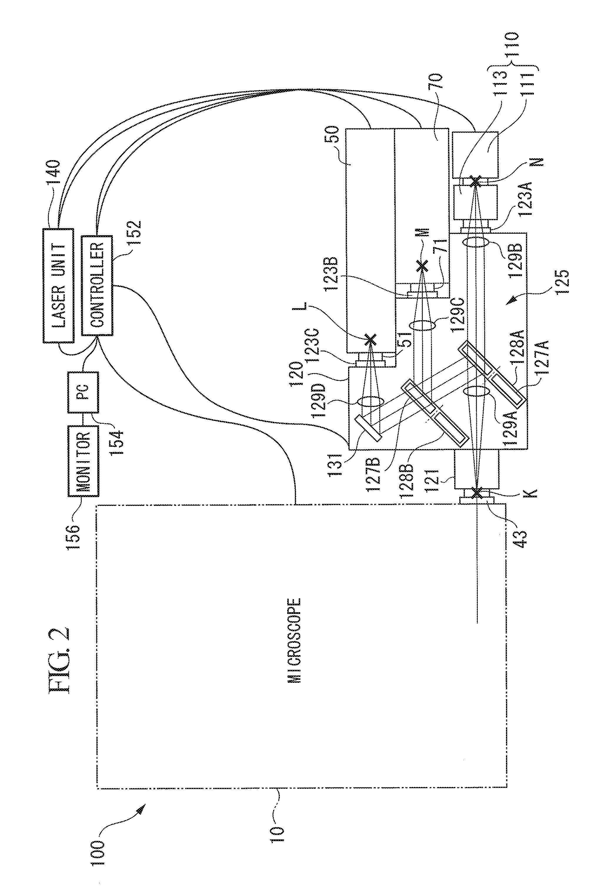
[0049]Now, a microscope connecting unit and a microscope system according to a first embodiment of the present invention will be described with reference to the drawings.

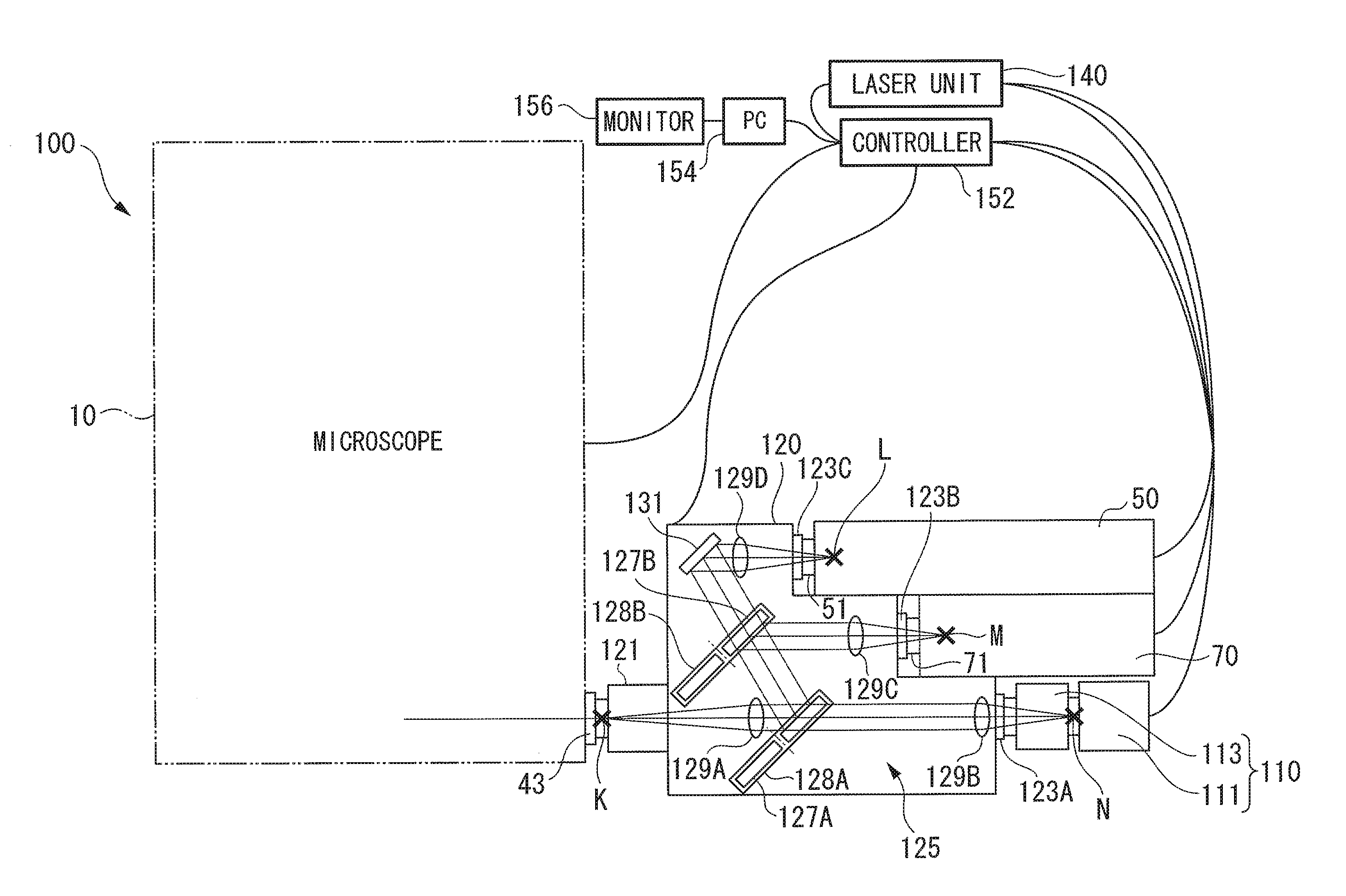
[0050]As shown in FIGS. 1 and 2, a microscope system 100 according to this embodiment includes a microscope 10 for visually observing a sample S, a laser unit (observation light source and stimulation light source) 140 that generates laser beams (observation excitation light and stimulation light), a confocal observation unit (detecting unit) 50 for performing confocal observation of the sample S, a stimulating unit (irradiating unit) 70 for stimulating the sample S with light, an image capturing unit (detecting unit) 110 for acquiring a two-dimensional image of the sample S, and a microscope connecting unit 120 for optically connecting the microscope 10 to the confocal observation unit 50, the stimulating unit 70, and the image capturing unit 110.

[0051]Furthermore, the microscope system 100 includes a controller (c...

second embodiment

[0108]Next, the microscope connecting unit 120 and a microscope system 200 according to a second embodiment of the present invention will be described.

[0109]As shown in FIG. 8, the microscope system 200 differs from the first embodiment in that it includes an observation high-speed laser scanning unit (DMD multipoint laser scanning unit, hereinafter simply referred to as a “multipoint scanning unit”) 210 that functions as both an illuminating unit and a detecting unit, instead of the image capturing unit 110.

[0110]In the following description, parts that are configured the same as those in the microscope system 100 according to the first embodiment are designated by the same reference signs, and a description thereof will be omitted.

[0111]As shown in FIG. 9, the multipoint scanning unit 210 includes a connector (unit connector) 211 that is connected to the first connection port 123A of the microscope connecting unit 120. Furthermore, the multipoint scanning unit 210 includes a first...


PUM


Abstract

Three or more devices can be connected to a microscope and can be used simultaneously. Provided is a microscope connecting unit including a microscope connection port that is connected to a microscope used to observe a sample; three or more unit connection ports to which a stimulating unit that irradiates the sample with light or a confocal observation unit or an image capturing unit that detects light generated at the sample is connectable; and two or more light-path combining units that are disposed between the microscope connecting port and the unit connection ports and that combine light paths optically connecting the microscope with the confocal observation unit, the stimulating unit, and the image capturing unit.

Description

BACKGROUND OF THE INVENTION[0001]1. Field of the Invention[0002]The present invention relates to microscope connecting units and microscope systems.[0003]This application is based on Japanese Patent Application No. 2009-245280, the content of which is incorporated herein by reference.[0004]2. Description of Related Art[0005]In a type of conventionally known microscope device, a camera or the like is attached to an eyepiece, making it possible to capture enlarged images of a sample as well as to visually observe the sample via an eyepiece lens (e.g., see the Publication of Japanese Patent No. 3069911 and Japanese Unexamined Patent Application, Publication No. 2004-318181). In the microscope device according to the Publication of Japanese Patent No. 3069911, a light path for images is integrated with a microscope. With a simple optical system, the device as a whole is made compact, and a stage on which a sample is placed is provided at a low position, serving to improve working effici...

Claims


Application Information

Patent Timeline
Patent Type & Authority Patents(United States)
IPC IPC(8): G02B21/00
CPCG02B21/0076G02B21/004G02B21/361G02B21/24G02B21/0032
Inventor ARAKI, MAKOTO
Owner EVIDENT CORP
Learn More