
Semiconductor device and method for producing the same

a technology of semiconductors and devices, applied in semiconductor devices, electrical equipment, transistors, etc., can solve the problems of prolonged treatment, decreased replacement of atmosphere in the furnace, so as to reduce the working efficiency of production equipment, prolong treatment, and increase the number of times

Active Publication Date: 2013-09-24
SHARP KK
View PDF16 Cites 0 Cited by
  • Summary
  • Abstract
  • Description
  • Claims
  • Application Information

AI Technical Summary

Benefits of technology

The present invention is aimed at providing a semiconductor device that can conduct electricity normally between wiring layers without the need for complicated and expensive maintenance or production apparatus. The invention inhibits the growth of natural oxide films and uses a reducing gas that has minimal corrosive properties. This results in reduced maintenance costs, increased efficiency of production, and faster replacement of the atmosphere in the furnace before deposition of the upper wiring layer. Overall, the invention improves the manufacturing process for semiconductor devices.

Problems solved by technology

Since the reducing gas has corrosive properties in Patent Documents 1 to 5, maintenance of piping, valves, filters, and the like of the production apparatus is complicated, and increased number of times of the maintenance is needed, leading to decrease of working efficiency of the production apparatus.
In addition, replacement of the atmosphere in the furnace before the deposition of the upper wiring layer takes time, and therefore treatment is prolonged.
As a result, costs are increased.
Therefore, the production apparatus is complicated and increased in size.
In Patent Document 8, the production apparatus itself is simpler, but the effect is restrictive, because the natural oxide film that grows on a lower wiring layer while the silicon substrate is carried from an apparatus for preliminary treatment such as HF cleaning to an apparatus for the formation of the upper wiring layer cannot be inhibited.
Furthermore, when the temperature is reduced to 150° C. or lower, the upper wiring layer attached to an inner wall of the reaction chamber peels off due to stress, which can be a cause of dust to be generated in the reaction chamber.

Method used


Image

  • Semiconductor device and method for producing the same
  • Semiconductor device and method for producing the same
  • Semiconductor device and method for producing the same

Examples


embodiment 1

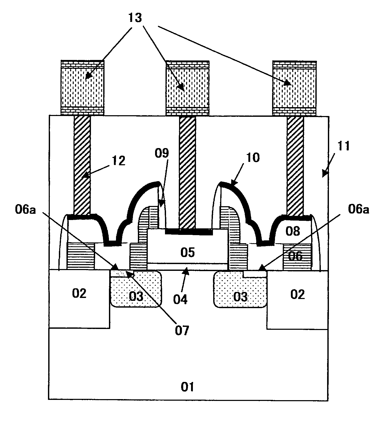
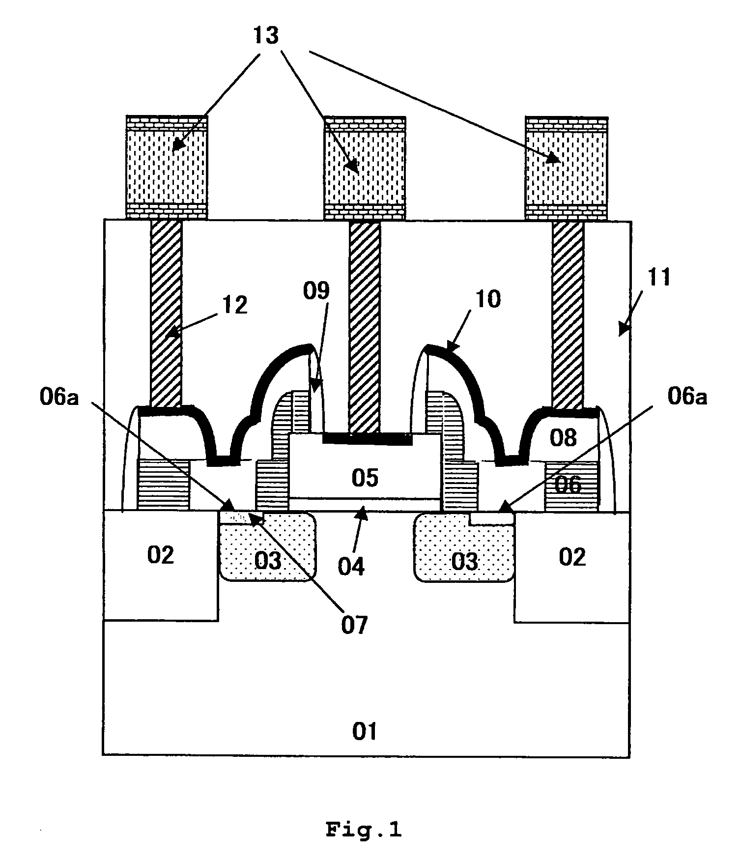
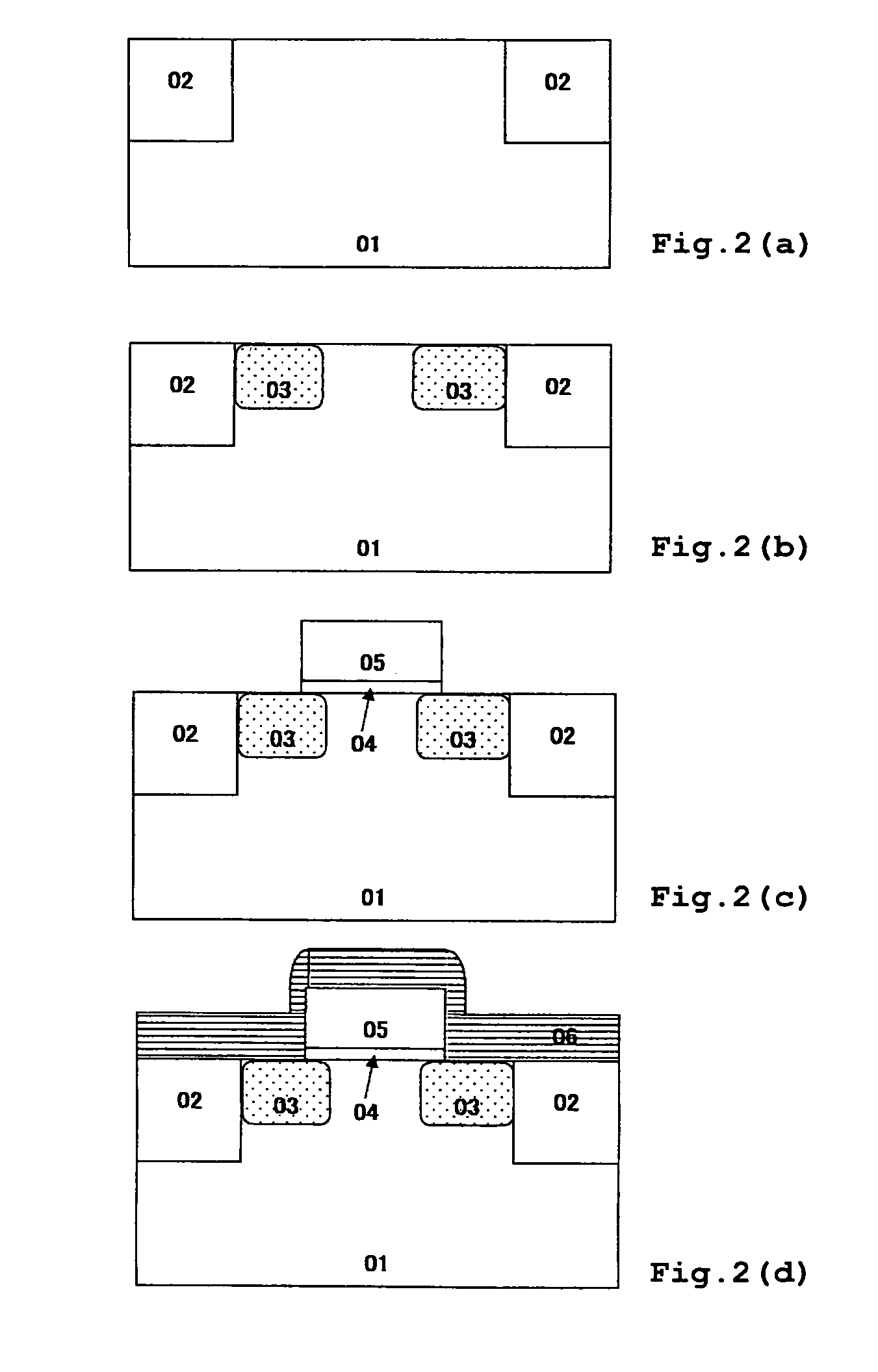
[0036]Embodiment 1 will be described with reference to FIG. 1 to FIG. 3 (e). FIG. 1 is a schematic cross sectional view of a semiconductor device of Embodiment 1; and FIG. 2(a) to FIG. 3(e) are schematic cross sectional views illustrating steps of a method for producing the semiconductor device of FIG. 1.

[0037]First, trenches (for example, 0.1 μm to 1 μm in depth, 0.07 μm to 1 μm in width) are dug in a silicon substrate 01 and an insulator (for example, silicon oxide) is embedded therein, thereby forming STI (Shallow Trench Isolation) layers 02 (see FIG. 2(a)). A LOCOS (Local Oxidation of Silicon) layer can be formed instead of the STI layer.

[0038]Next, drift layers 03 in a relatively low concentration (for example, 1×10¹⁴ / cm3 to 1×10²⁰ / cm3) are formed by ion implantation (for example, impurities: phosphorus, arsenic, antimony, boron, aluminum, gallium, indium) (see FIG. 2(b)).

[0039]Further, a silicon oxide layer (for example, 2 nm to 50 nm in thickness) and a polysilicon layer (for...


PUM


Abstract

A semiconductor device comprising at least two wiring layers on a substrate or a surface layer of the substrate, wherein a lower wiring layer of the two wiring layers contains silicon, and a silicon carbide layer is placed between the lower wiring layer and an upper wiring layer.

Description

CROSS-REFERENCE TO RELATED APPLICATION[0001]This application is related to Japanese application No. 2008-298163 filed on Nov. 21, 2008, whose priority is claimed under 35 USC §119, the disclosure of which is incorporated by reference in its entirety.BACKGROUND OF THE INVENTION[0002]1. Field of the Invention[0003]The present invention relates to a semiconductor device and a method for producing the same. More particularly, the present invention relates to a semiconductor device comprising at least two wiring layers and having a structure in which electric conduction between the two wiring layers can be ensured when a lower wiring layer of the two wiring layers is composed of silicon, and to a method for producing the semiconductor device. In particular, the present invention can be suitably used for a stacked transistor which comprises: a pair of drift layers being formed on a surface layer of a silicon substrate and having a channel therebetween; and a source / drain laminated on the ...

Claims


Application Information

Patent Timeline
Patent Type & Authority Patents(United States)
IPC IPC(8): H01L29/78H01L21/336
CPCH01L21/26506H01L29/165H01L29/41783H01L29/66568H01L29/7833H01L29/665
Inventor TAJIRI, MASAYUKI
Owner SHARP KK
Learn More