Dual powered propulsion system

a propulsion system and dual-power technology, applied in the direction of steering devices, chain/belt transmissions, vehicle components, etc., can solve the problems of unstable control of the rider's bicycle, lack of power provided by the rider, etc., to improve the efficiency of the body's lactate uptake, and the effect of heavy loads

Active Publication Date: 2017-02-28
FELKER THOMAS S
View PDF83 Cites 1 Cited by
  • Summary
  • Abstract
  • Description
  • Claims
  • Application Information

AI Technical Summary

Benefits of technology

[0010]This invention provides the ability of the rider to contemporaneously input 100% of his power from a) the “up and down” curling motion of his arms pumping the forearm / hand bars, combined with b) rotational movement of his legs and feet on the Pedals into forward locomotion of the Crank Axle and Rear Wheel of the Bicycle or other vehicle containing this invention. During both the “pull” and “push”, or “up” and “down” movement of the Forearm / hand Bars, 100% of his arm power is inputted into the forward rotation of both the Crank Axle and vehicle's driving wheel. Simultaneously, full control for steering the bicycle is provided by virtue of the arm power being delivered only through a vertical and rotating movement of his arms and Forearm / hand Bars, which are connected directly to the Stem, Turning Rod and pivot Fulcrum. Through use only of the rotating “up and down” movement of the Forearm / hand Bars to provide power by the rider, there is no unintended lateral movement of the rider's arms during the power strokes of his Forearm / hand Bars, and hence the rider has complete control and stability of his or her Bicycle. At the same time as the rider can turn the Bicycle toward his left or right direction, he can simultaneously provide Dual Power into the Crank Axle from pedaling his legs.
[0012]The Dual Powered Bicycle described herein is designed to improve many facets involved in the riding of a combined arms and legs powered bicycle design, as compared to a bicycle in which the rider uses only power from his legs, to rotate the Crank Axle. Some of these improved facets include, but are not limited to: a) improving the efficiency of the body's lactate uptake by spreading-out over more muscle groups of the body the energy utilized in the locomotion of the vehicle, b) providing a more complete exercise program for the rider by utilizing more muscle groups of the body, c) permitting the rider to ride the bicycle faster through the implementation of additional muscle groups to provide more energy into the Crank Axle and driving wheel, d) permitting the rider to carry heavier loads by utilizing more muscle groups to power the driving wheel of the bicycle, and e) permitting the rider to have a more efficient usage of the available oxygen in his body by spreading it out over more active muscle groups during a given period of riding time than when the rider is using just his legs. These benefits are a result of the application of the following new Dual Power concepts from this invention: a) using up to 100% of the amount of energy being exerted into the arc shaped “down-stroke” of the pumping “Forearm / hand Bars,” b) affixing in place the rider's forearms and elbows onto the top of the upper surface of the Forearm Platforms to increase the amount of arm power being delivered into the Crank Axle as a result of the rider's forearms and elbows being held firmly affixed to the upper surface of the Forearm Platforms during the “down” stroke of the arc shaped “up and down” pumping cycles, c) the transfer of power from arc shaped “up and down” cycling of the Forearm / hand Bars into a Push / Pull Flexible Cable System consisting on each end of it a lineally moving Telescoping Rod located inside its respective Support Tube, with the internal ends of each Telescoping Rod attached to the opposite end of the Flexible Sliding Cable, d) a Flexible Cable System located between the two Support Tubes and consisting of a Stationary but Flexible Cable Sheath and Flexible Cable sliding “back and forth” inside the Cable Sheath in unison with the “up and down” pumping Forearm / hand Bars, e) lineally moving an oscillating Connecting Bridge Rod that connects the Lower Rear Telescoping Rod with the rear Flywheel, f) use of a One-way Bearing Clutch Flywheel connected to a Rear Upper Axle, and such axle also being attached to an Upper Rear Sprocket, and g) the Upper Rear Sprocket is connected by a Chain to the rotating Crank Axle.
[0077]e) Means of connecting the rear Rod Support Sleeve to both the Upper and Lower Hubs;This Cable System serves at least the following two primary purposes that are integral to this invention: 1) Precludes the Flexible Sliding Internal Cable from coming apart or bursting outside its Sheath while sliding under power in the “down” or “compression” stroke of the Forearm / hand Bars; and 2) Because both the Sliding Internal Cable and the External Stationary Flexible Cable Sheath are flexible, this permits the rider to control the bicycle by turning its Front Wheel to the right or left, while at the same time pumping the Forearm / hand Bars in an arc shape “up and down”, thereby providing rotational power to the Crank Axle;

Problems solved by technology

U.S. Pat. No. 5,328,195 does not provide for any power from the rider being delivered to the crank axle when the forearms and hands of the rider are “pushing down” on the movable forearm / hand bars during his “up and down” cycle.
While some of these various types of Dual Powered vehicles have had modest acceptance in the marketplace, they have been deficient because they cause excess resistance and friction-loss in transmitting energy from the moving handle bars to the crank axle, they are clumsy to operate, they only provide energy into the crank axle during the pulling or upward movement of the handle bars, and at high speeds some of the designs can cause the rider's control of the bicycle to be unstable.

Method used


Image

  • Dual powered propulsion system
  • Dual powered propulsion system
  • Dual powered propulsion system

Examples


Embodiment Construction

[0129]In the following description and accompanying drawings, like numbers refer to like parts whenever they occur.

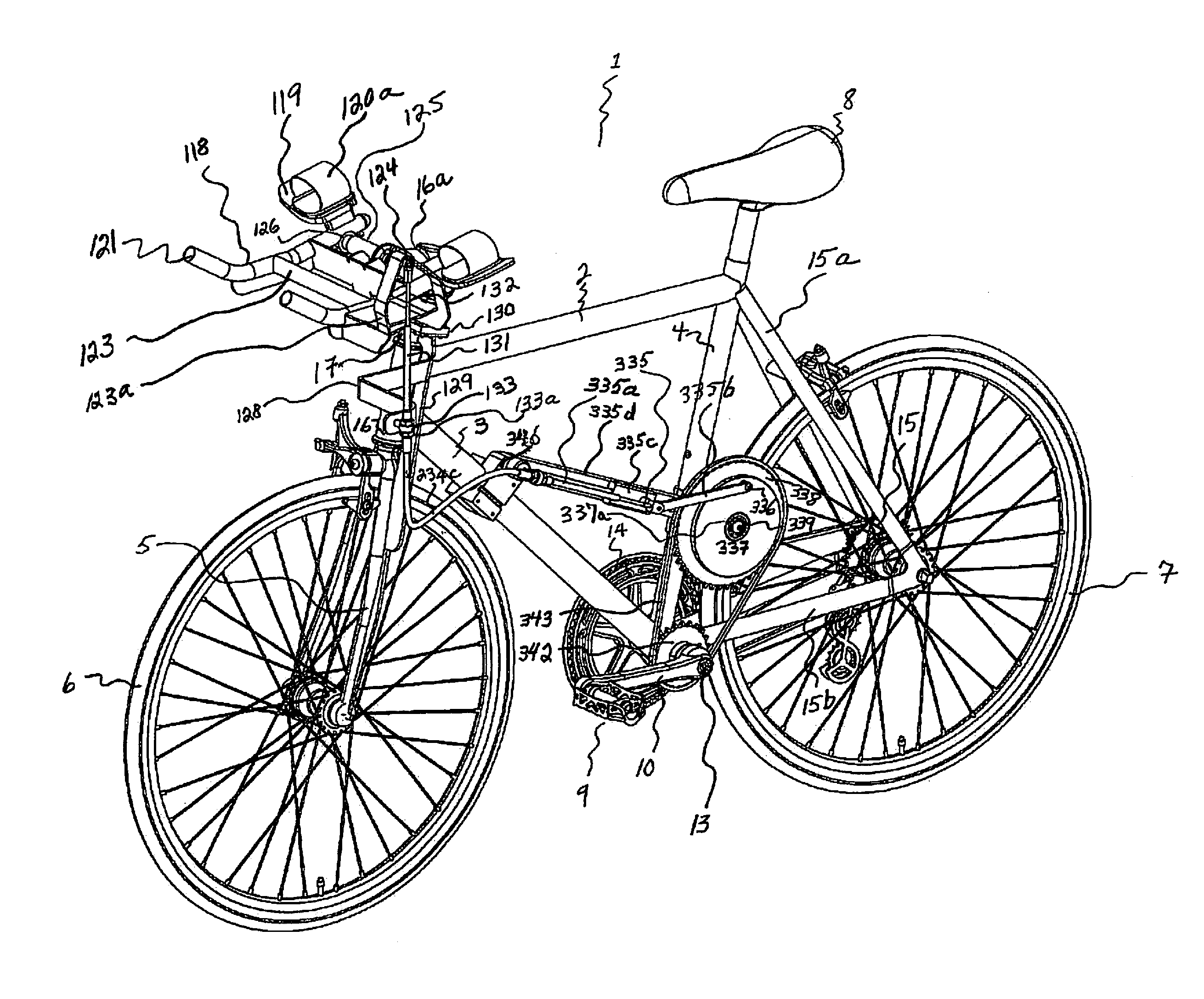
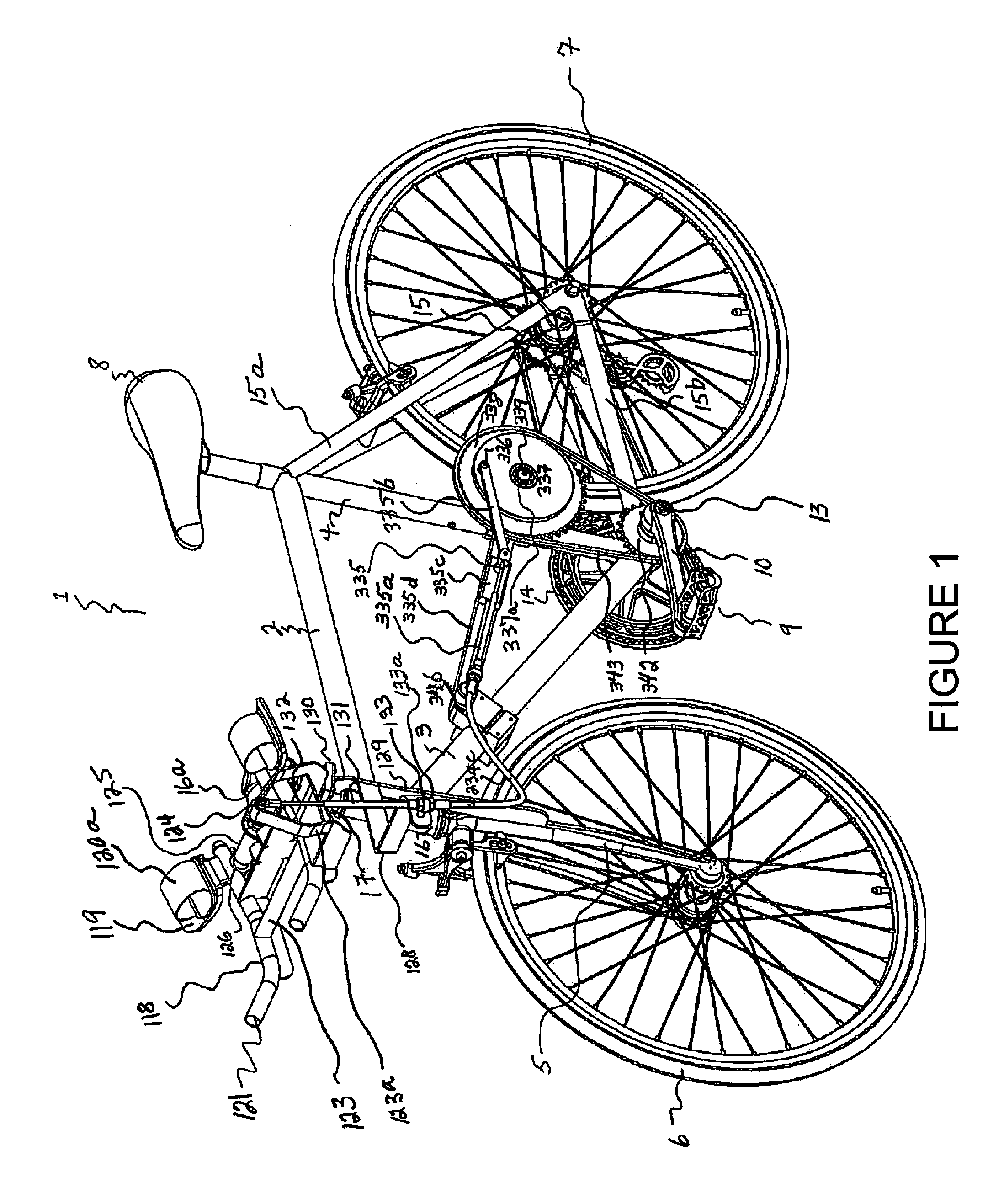
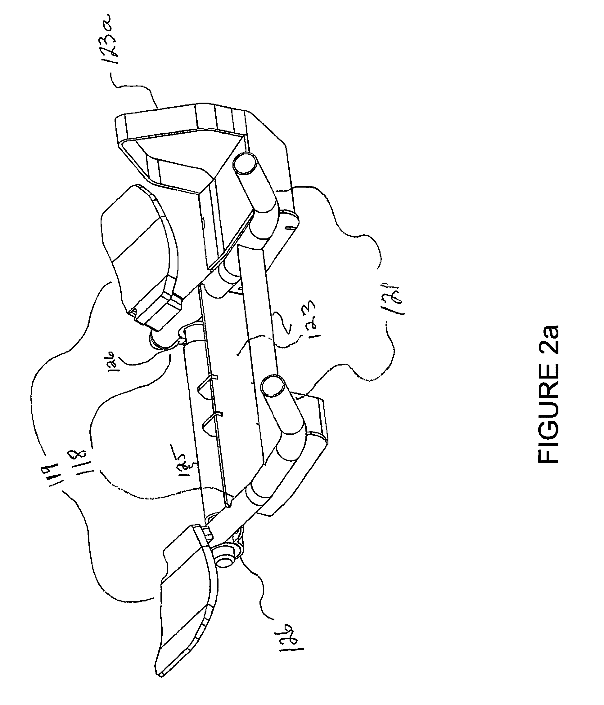
[0130]The Dual Power Bicycle consists of Bicycle Frame 1, and has attached to its Turning Tube 17 a perpendicularly mounted Fulcrum Rod 125. This Fulcrum Rod 125 serves two purposes, a) provides the rider with the ability to steer the front wheel 6 of the bicycle with his forearms and hands by causing the Turning Tube 17 to naturally steer right or left when he turns it with the Forearm / hand Bars 118, which are attached to the Fulcrum Rod 125, and b) permits the rider to simultaneously input 100% of his power into the Crank Axle 13 from rotationally pumping “up and down” the Forearm / hand Bars 118. The Fulcrum Rod 125 has on each end of it a Bearing 126, and attached to each of these Bearings 126 is the rear end of one of two Forearm / hand Bars 118. Thus, as the rider “pulls-up and pushes-down” the Forearm / hand Bars 118, the rear end of each of these Forearm / hand Bars 118...


PUM


Abstract

The present invention relates to a rider's simultaneous use of his forearms / hands and legs to provide dual power into a propulsion system for riding a cycle vehicle, including a bicycle and a tricycle, or other vehicles. The invention permits the rider to have complete control turning the cycle vehicle, at will, right or left, while at the same time pumping a set of forearm / hand bars in an up power stroke and a down power stroke. In addition, even though the pumping action is lineally moving a telescoping rod and a push / pull cable back and forth, it is also simultaneously rotating a flywheel, upper and lower sprockets, and the crank axle to drive the bicycle wheel forward over the riding surface. Thus, the rider can provide maximum power into rotating the rear tire by simultaneously using both his arms and legs, while contemporaneously controlling his direction of travel.

Description

BACKGROUND[0001]1. Technical Fields[0002]This invention relates generally to a dual powered bicycle and more particularly to a device for using the rider's arms to supplement power provided by his natural or prosthetic legs pedaling a bicycle to propel the rear wheel as it travels over the ground.[0003]2. Discussion of Related Art[0004]Human powered vehicles employing many different designs for providing human energy to cause movement of the rider's vehicle have been developed and used throughout the ages. These types of vehicles have been used in many activities, including but not limited to sports, riding to work or store, movement of goods and passengers in commerce, physical exercise or other task. The types of vehicles that can utilize the benefits of a combined arm and leg powered crank axle include, but are not limited to, bicycles, tandem bicycles, tricycles, human powered airplanes, human powered helicopters, and water craft.[0005]Current and past variations of combined arm...

Claims


Application Information

Patent Timeline
Patent Type & Authority Patents(United States)
IPC IPC(8): B62M1/12B62M9/00
CPCB62M1/12B62M2009/005B62K21/125
Inventor FELKER, THOMAS S.
Owner FELKER THOMAS S
Why Eureka
Try Eureka