Cable connector assembly with spacer

a technology of connector assembly and spacer, which is applied in the direction of contact member assembly/disassembly, fixed connection, two-part coupling device, etc., can solve the problem of difficult soldering of wires, and achieve the effect of easy soldering process and easy cutting

Inactive Publication Date: 2017-02-28
FOXCONN INTERCONNECT TECH LTD
View PDF10 Cites 5 Cited by
  • Summary
  • Abstract
  • Description
  • Claims
  • Application Information

AI Technical Summary

Benefits of technology

[0007]Accordingly, an object of the present invention is to provide a cable connector assembly having a cable with a plurality of coaxial wires and a plurality of unshielded wires. The cable connector assembly includes an insulative housing with a front tongue and a rear end, a plurality of contacts with mating portions exposed on the front tongue and connecting portions exposed on the rear end, and a spacer assembled to the rear end. The spacer forms a plurality of positioning holes extending therethrough along a front-to-back direction, and a passageway extending therethrough along a vertical direction perpendicular to the front-to-back direction. The coaxial wires are inserted through the corresponding positioning holes and across the passageway to reach the corresponding contacts along the front-to-back direction so as to cut the coaxial wires in the passageway along the vertical direction. Notably, the coaxial wires are retained to the spacer and across the passageway for an easy soldering process and an easy cut process.

Problems solved by technology

Since the wires are not retained to any spacer, it is difficult to solder the wires.

Method used


Image

  • Cable connector assembly with spacer
  • Cable connector assembly with spacer
  • Cable connector assembly with spacer

Examples


Embodiment Construction

[0015]Reference will now be made in detail to some preferred embodiments of the present invention.

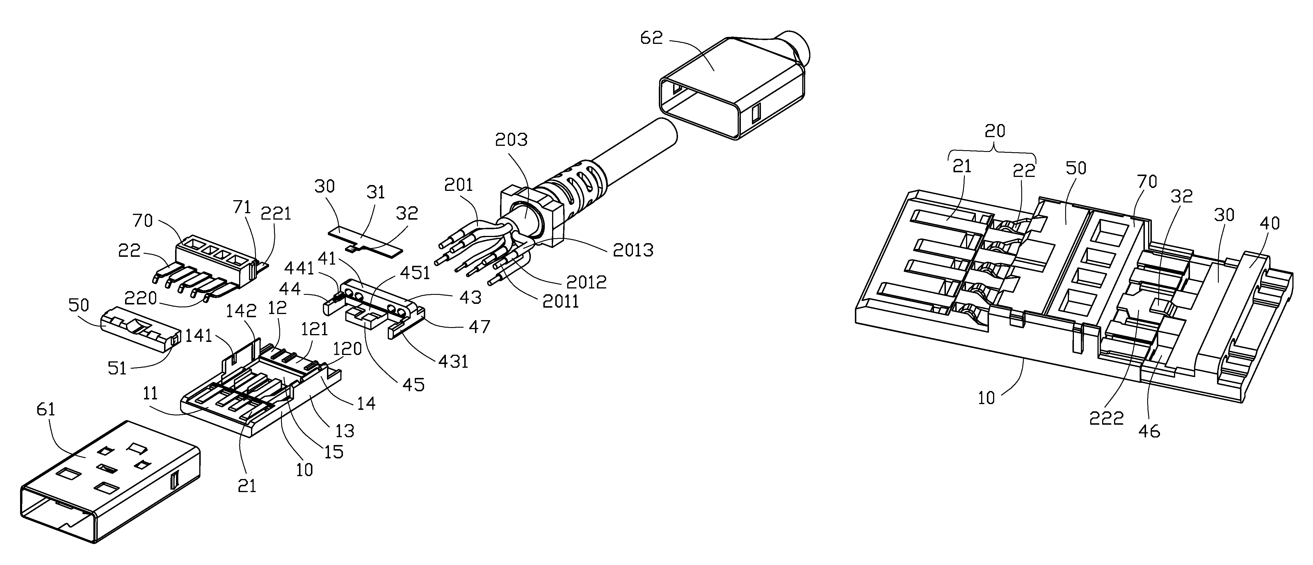
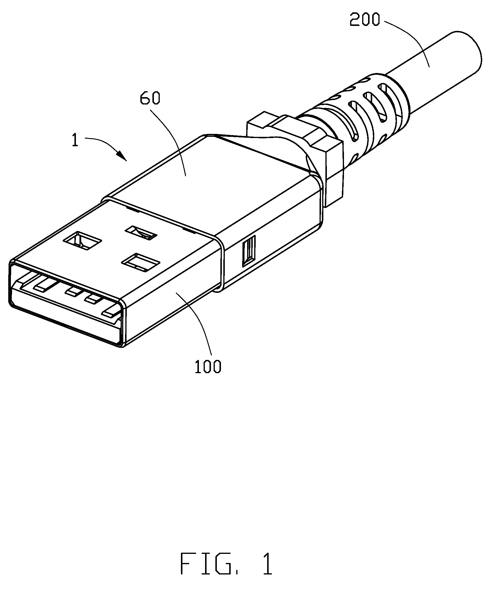
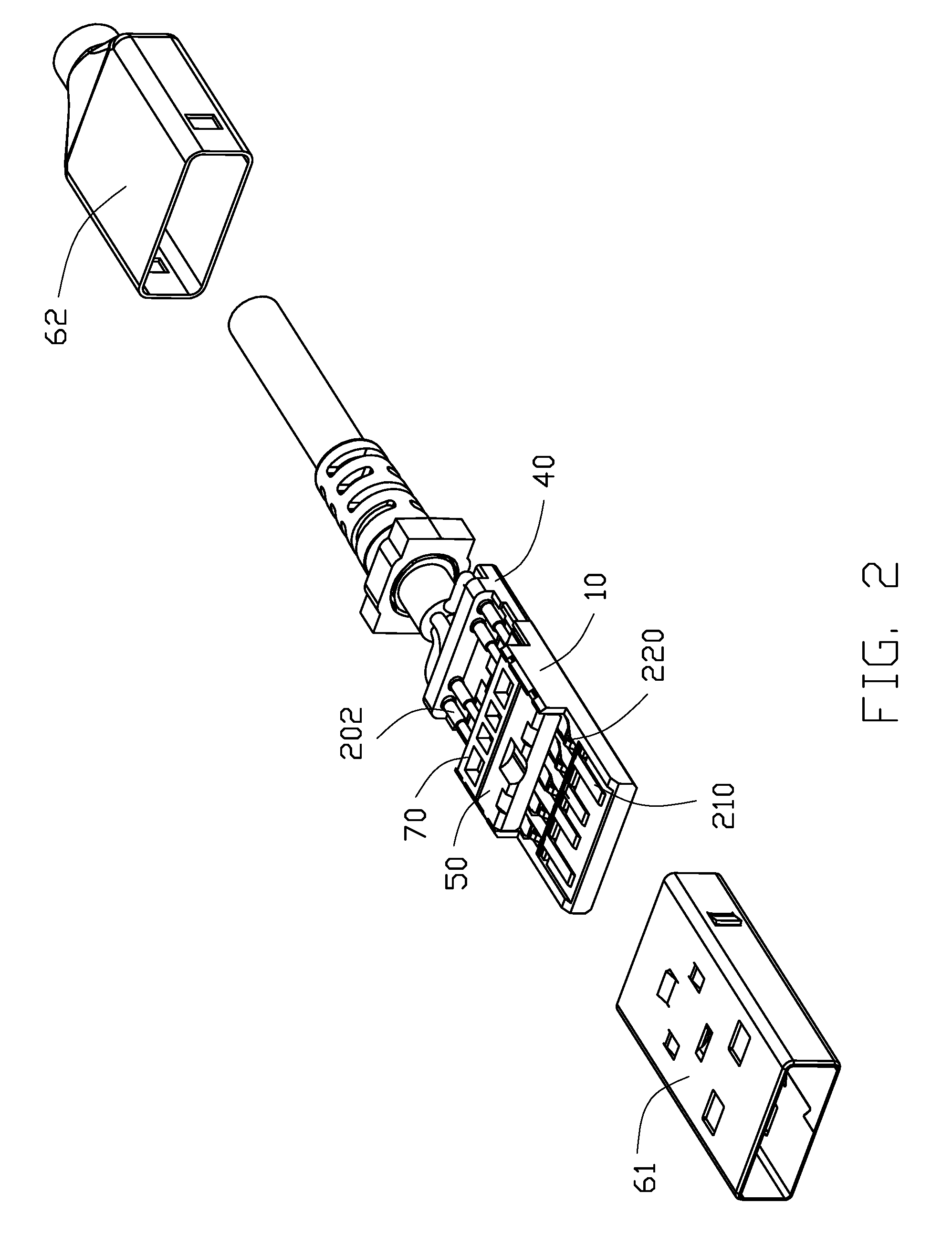
[0016]FIGS. 1 to 6 show a cable connector assembly 1 including a connector 100 and a cable 200. The connector 100 including an insulative housing 10 with a front section 11, a rear section 12, and a middle section 13 located therebetween. The front section 11 is a mating tongue with a mating surface thereon. A plurality of partitions 120 protrude upwardly from a top surface of the rear section 12. Each pair of neighbored partitions 120 defines an upward groove 121 therebetween. A pair of side projections 14 are formed on two opposite sides of the middle portion 13 and extend upwardly beyond the partitions 120 and the front section 11. A mounting cavity 15 is defined by the side projections 14. Each of the side projections 14 defines a first assembling groove 141 and a second assembling groove 142 extending in a vertical direction, wherein the second assembling groove 142 is disposed beh...


PUM


Abstract

A cable connector assembly has a connector and a cable with a number of coaxial wires and a number of unshielded wires. The connector includes an insulative housing with a front tongue and a rear end, a number of contacts with mating portions exposed on the front tongue and connecting portions exposed on the rear end, and a spacer assembled to the rear end. The spacer forms a plurality of positioning holes extending therethrough along a front-to-back direction, and a passageway extending therethrough along a vertical direction perpendicular to the front-to-back direction. The coaxial wires are inserted through the corresponding positioning holes and across the passageway to reach the corresponding contacts along the front-to-back direction so as to cut the coaxial wires in the passageway along the vertical direction.

Description

BACKGROUND OF THE INVENTION[0001]1. Field of the Invention[0002]The present invention relates to a cable connector assembly, and more particularly to a cable connector assembly having a spacer to sort out and regulate the wires of a cable.[0003]2. Description of Related Arts[0004]U.S. Pat. No. 8,303,329 discloses a cable connector assembly having a connector and a cable. The connector includes an insulative housing, a plurality of contacts assembled to the insulative housing, and a metallic shell enclosing the insulative housing and the contacts. The cable includes a plurality of conductive wires mechanically and electrically connected to tail sections of the contacts by way of insulation displacement contact.[0005]U.S. Pat. No. 8,721,361 discloses a cable connector assembly including a plurality of conductive wires mechanically and electrically connected to tail sections of corresponding contacts via a soldering process. Since the wires are not retained to any spacer, it is difficu...

Claims


Application Information

Patent Timeline
Patent Type & Authority Patents(United States)
IPC IPC(8): H01R13/642H01R13/6585H01R43/20H01R9/24H01R12/59H01R12/77
CPCH01R13/6585H01R13/642H01R43/20H01R9/2416H01R12/596H01R12/775H01R24/62
Inventor XING, DA-WEICHEN, JUNWU, JERRY
Owner FOXCONN INTERCONNECT TECH LTD
Why Eureka
Try Eureka