Expandable spinal interbody spacer and method of use

a technology of expanding spinal interbody and spacer, which is applied in the field of expanding spinal implants, can solve the problems of conventional prosthetic implants being dislodged or moved from the desired implantation location, and the collapse of normal occupied space between adjacent vertebrae, etc., and achieves the desired lordosis. , to achieve the effect of the desired lordosis

Active Publication Date: 2017-03-07
K2M
View PDF36 Cites 61 Cited by
  • Summary
  • Abstract
  • Description
  • Claims
  • Application Information

AI Technical Summary

Benefits of technology

[0012]In aspects, the spinal implant further includes a ratchet screw rotatably supported within an annular groove defined within the lower body. The ratchet screw includes a head and threaded shank extending therefrom and is threadably engaged within a threaded through-hole defined through the ratchet mechanism. Rotation of the ratchet screw in a first direction effectuates movement of the ratchet mechanism in a first direction, and rotation of the ratchet screw in a second, opposite, direction effectuates movement of the ratchet mechanism in a second, opposite, direction.
[0022]In aspects, locking the ratchet mechanism includes rotating a ratchet screw disposed within an annular groove defined within the upper body in a first direction, wherein the ratchet screw includes a head and a threaded shank extending therefrom. The ratchet screw is threadably engaged within a threaded through-hole defined through the ratchet mechanism. Rotating the ratchet screw effectuates movement of the ratchet mechanism in a first direction thereby causing the ratchet mechanism to engage the lower body and lock the position of the lower body relative to the upper body.
[0024]In aspects, locking the ratchet mechanism further includes further rotating the ratchet screw the first direction, causing the first and second pluralities of teeth to further engage, thereby locking the position of the upper body and the lower body relative to each other.

Problems solved by technology

After a partial or complete discectomy, the normally occupied space between adjacent vertebral bodies may collapse and / or become misaligned due to the absence of all or a part of the intervertebral disc.
However, there exists a possibility that conventional prosthetic implants may be dislodged or moved from their desired implantation location due to movement by the patient before sufficient bone growth has occurred.
Additionally, achieving the desired lordosis can be difficult given the limitations of typical prosthetic implants once they are implanted.

Method used


Image

  • Expandable spinal interbody spacer and method of use
  • Expandable spinal interbody spacer and method of use
  • Expandable spinal interbody spacer and method of use

Examples


Embodiment Construction

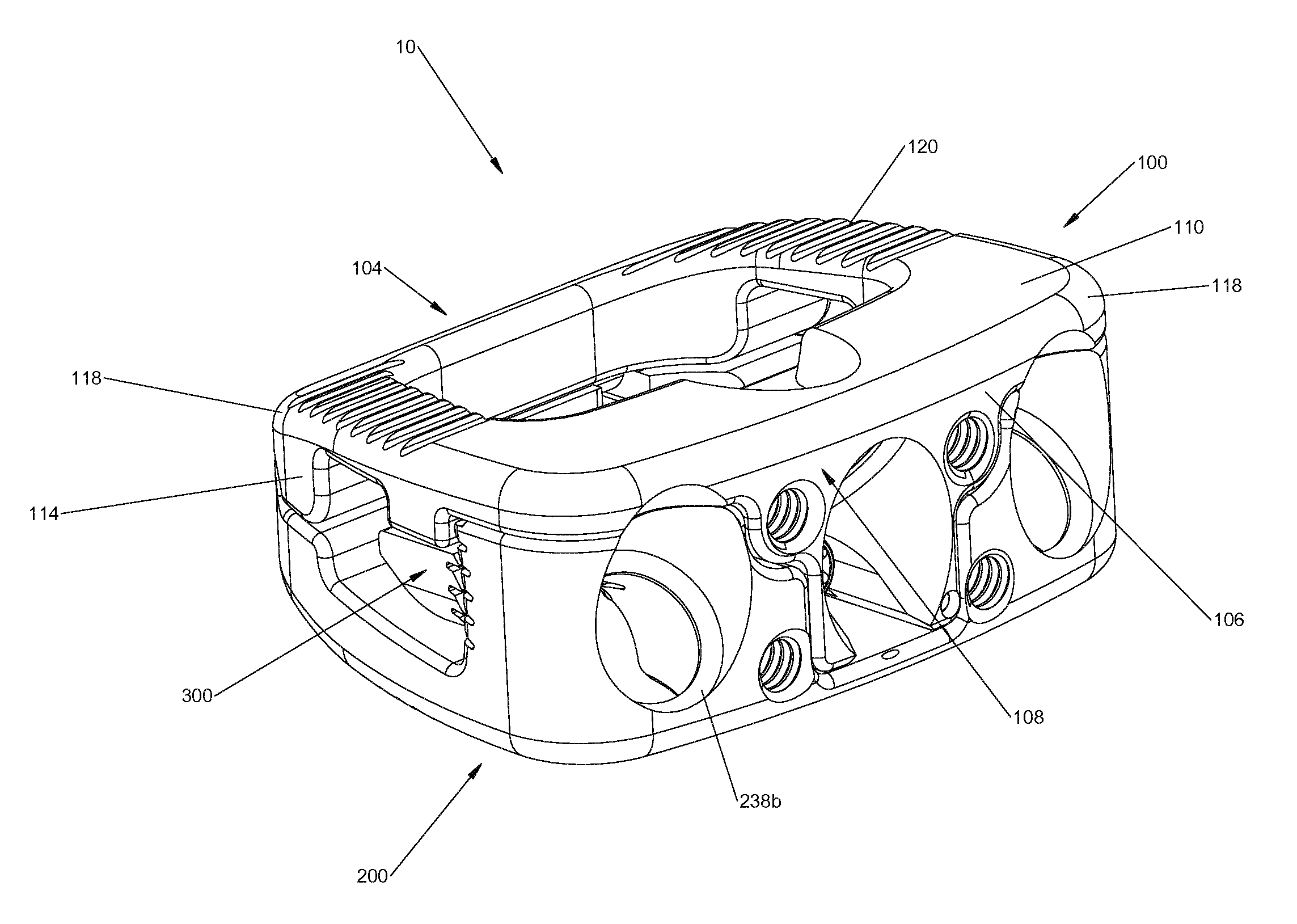
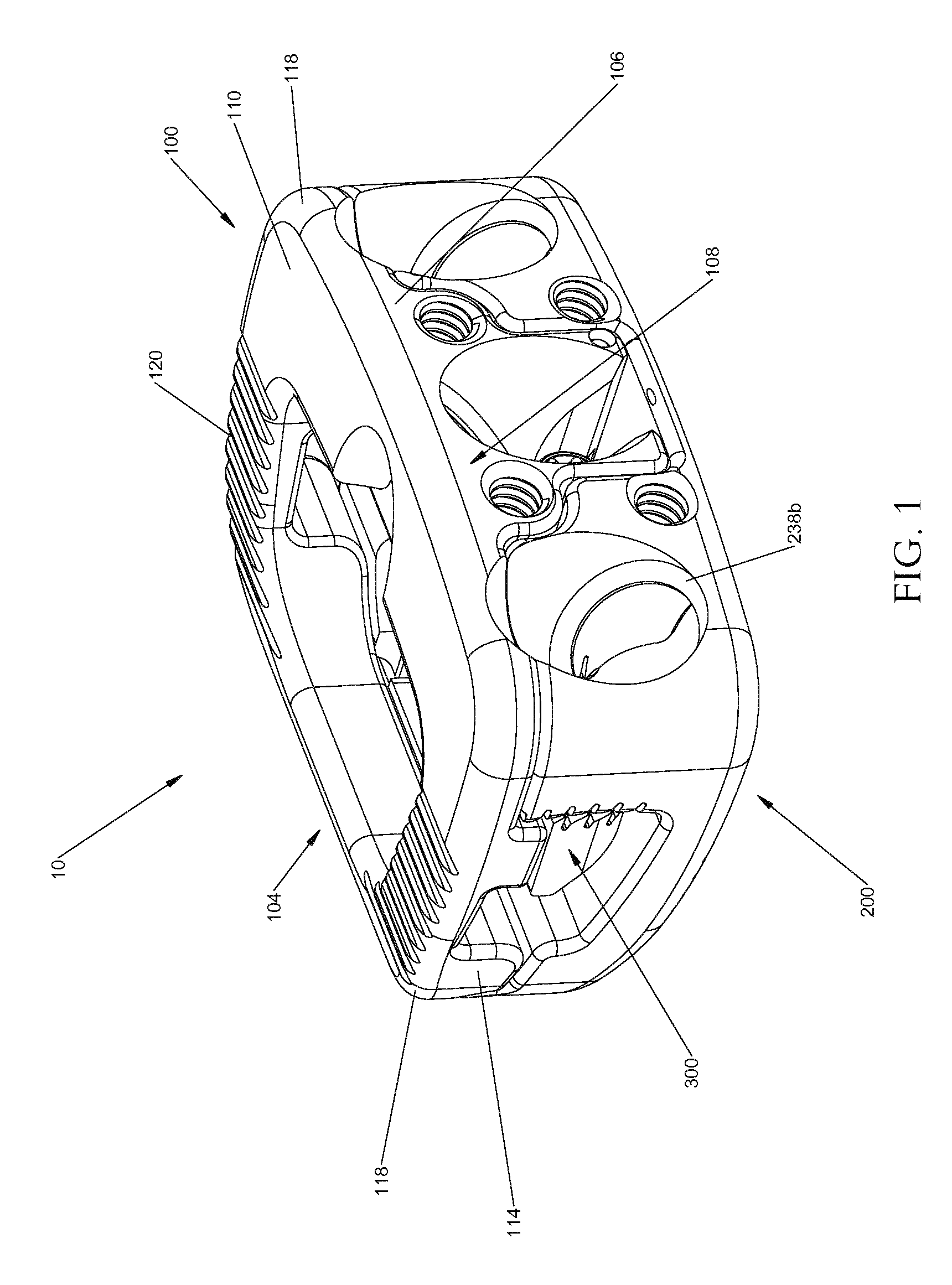
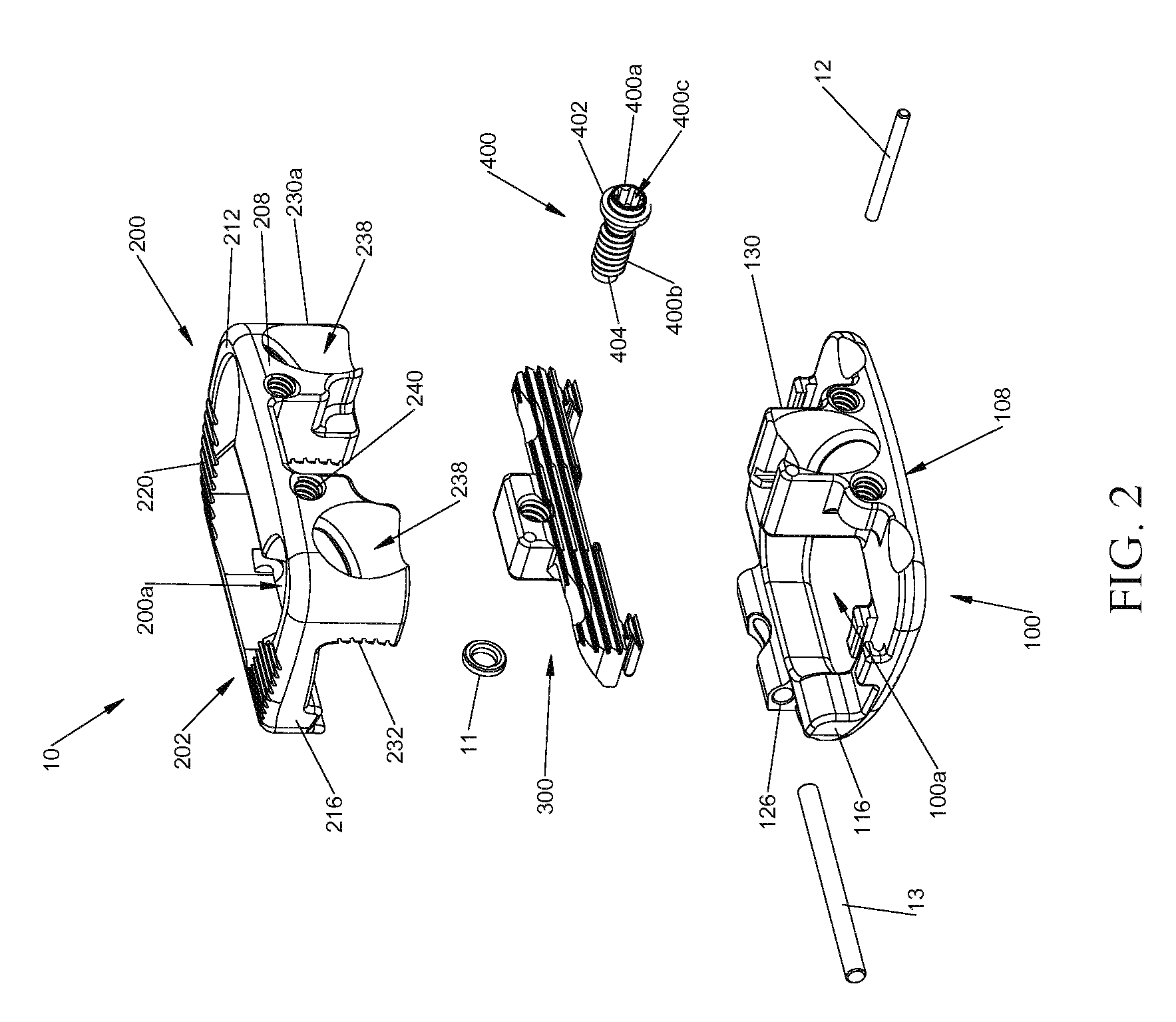
[0050]Embodiments of the present disclosure are now described in detail with reference to the drawings in which like reference numerals designate identical or corresponding elements in each of the several views. As used herein, the term “clinician” refers to a doctor, a nurse or any other care provider and may include support personnel. Throughout this description, the term “proximal” will refer to the portion of the device or component thereof that is closer to the clinician and the term “distal” will refer to the portion of the device or component thereof that is farther from the clinician. Additionally, in the drawings and in the description that follows, terms such as front, rear, upper, lower, top, bottom, and similar directional terms are used simply for convenience of description and are not intended to limit the disclosure. In the following description, well-known functions or constructions are not described in detail to avoid obscuring the present disclosure in unnecessary ...


PUM


Abstract

An expandable spinal implant configured for positioning within a space between adjacent vertebral bodies includes an upper body, a lower body, a ratchet mechanism, and a plurality of bone screws. The upper body and lower body are pivotably affixed at a first end and are capable of movement relative to each other. The ratchet mechanism is slidably disposed on one of the upper and lower body and is capable of engaging the opposite one of the upper and lower body thereby permitting movement of the upper and lower body relative to each other in a first direction, but not in a second direction. An insertion instrument capable of being attached to the expandable spinal instrument and a method of performing spinal surgery is also disclosed.

Description

BACKGROUND[0001]Technical Field[0002]The present disclosure relates generally to devices and methods for treating spinal conditions, and in particular, to expandable spinal implants configured for positioning within an intervertebral space.[0003]Background of the Disclosure[0004]After a partial or complete discectomy, the normally occupied space between adjacent vertebral bodies may collapse and / or become misaligned due to the absence of all or a part of the intervertebral disc. In these situations, a physician may insert one or more prosthetic spacers between the affected vertebrae to maintain normal disc spacing and / or the normal amount of lordosis in the affected region.[0005]Typically, a prosthetic implant is inserted between the adjacent vertebrae and may include pathways that permit bone growth between the adjacent vertebrae until they are fused together. However, there exists a possibility that conventional prosthetic implants may be dislodged or moved from their desired impl...

Claims


Application Information

Patent Timeline
Patent Type & Authority Patents(United States)
IPC IPC(8): A61F2/44A61F2/46A61F2/30
CPCA61F2/442A61F2/4455A61F2/4611A61F2002/30172A61F2002/30383A61F2002/30398A61F2002/30405A61F2002/30471A61F2002/30487A61F2002/30522A61F2002/30538A61F2002/30787A61F2002/30797A61F2002/30904A61F2002/4475A61F2002/4627A61F2220/0016A61F2002/30593A61F2/30771A61F2002/30579
Inventor SUDDABY, LOUBERTMCCLINTOCK, LARRYWASSINGER, ADAMJONES, SCOTTMOORE, JENNIFERDONOHOE, JOHN
Owner K2M
Why Eureka
Try Eureka