Oil level display device of engine

a display device and oil level technology, applied in the direction of lubrication indication devices, lubrication containers, lubrication elements, etc., can solve the problems of requiring a new design and installation, poor workability, and incompatibility of oil level display devices with conventional oil level gauges, so as to reduce the complexity of operations and ensure the amount of oil. the effect of reliable visual inspection

Inactive Publication Date: 2017-03-07
SUBARU CORP
View PDF34 Cites 3 Cited by
  • Summary
  • Abstract
  • Description
  • Claims
  • Application Information

AI Technical Summary

Benefits of technology

[0008]In the light of the above, it is an object of the present invention to provide an oil level display device of an engine that reduces complicated operations such as insertion and removal of a conventional oil level gauge while securing compatibility with a conventional oil level gauge, and that enables reliable visual checking of the amount of oil.

Problems solved by technology

Such oil level gauges have a drawback in that the operator must insert and remove manually the gauge in order to check the amount of oil.
In particular, when various devices are disposed around the engine, the position of the oil level gauge is at the bottom and thus difficult to reach, whereby workability becomes poor.
While the oil level display device disclosed in JP-A No. 2005-134256 can remove complicated operations such as gauge insertion and removal incurred in conventional oil level gauges can thus be dispensed with, the oil level display device is not compatible with conventional oil level gauges, and requires a new design and new installation.
This may result in an increase in cost and cause a problem in engine mounting layout.

Method used


Image

  • Oil level display device of engine
  • Oil level display device of engine
  • Oil level display device of engine

Examples


Embodiment Construction

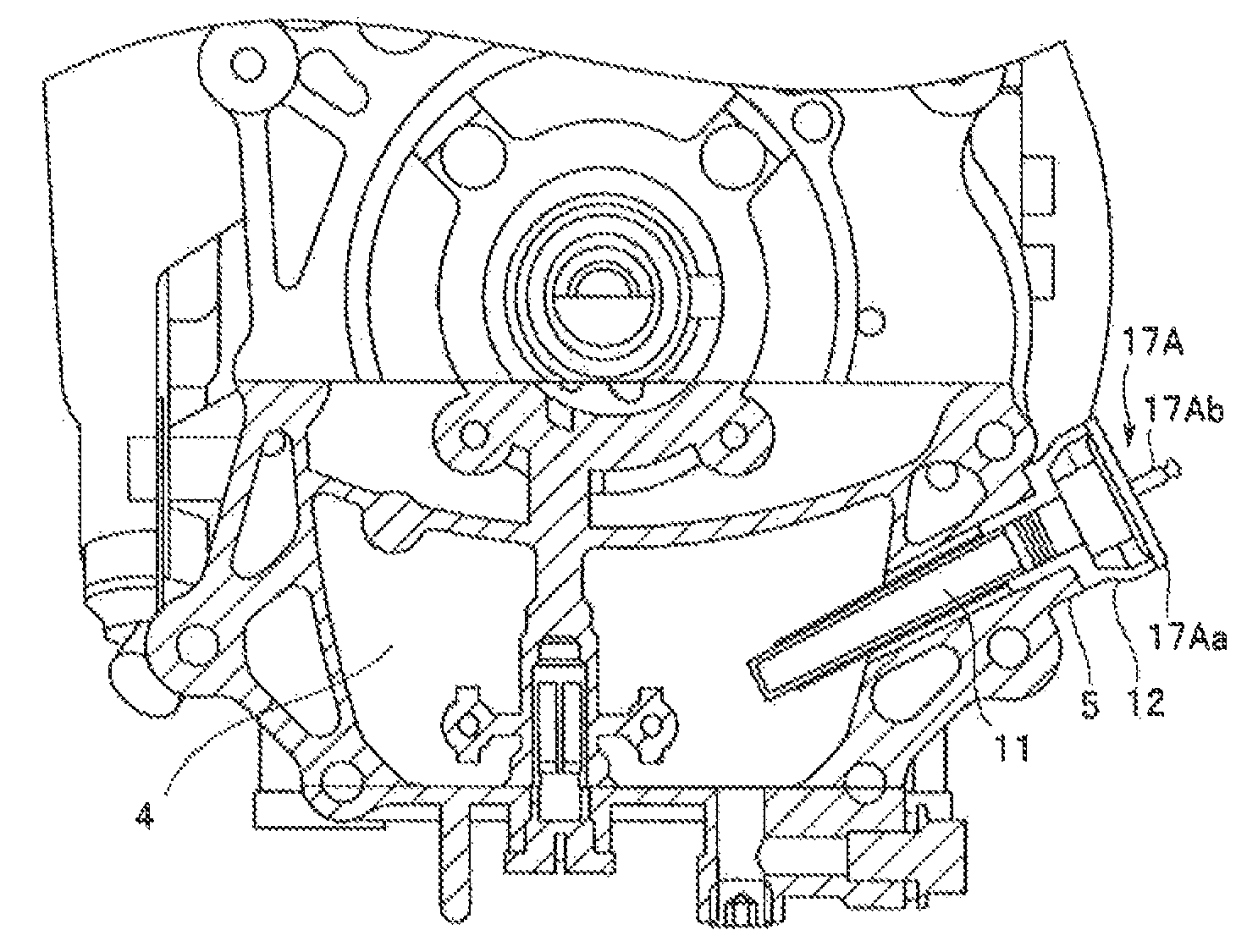
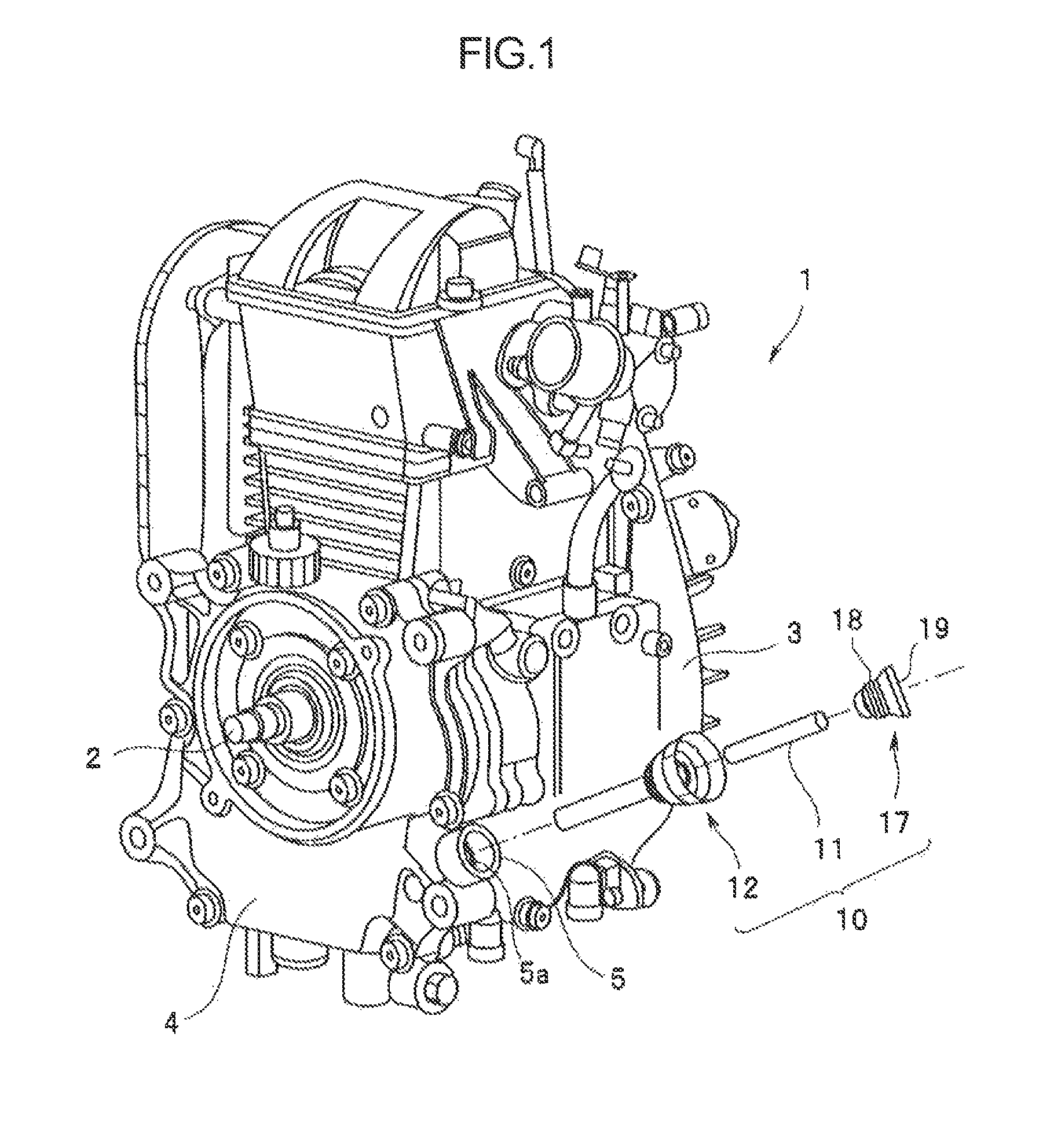
[0017]Examples of the present invention are explained next with reference to accompanying drawings. In FIG. 1, the reference symbol 1 denotes a utility engine that is used, as a prime mover, in, for instance, generators, working equipment, snowmobiles or the like. In the figure, the engine is an engine for construction machinery, such as a rammer or the like. An oil pan 4 that stores oil for lubricating various units is formed at the bottom of a crank case 3 that supports a crankshaft 2 of the engine 1. The oil stored in the oil pan 4, is supplied, in the form of oil spray or mist, to a cylinder inner wall, the crankshaft 2, and a valve operating mechanism of the cylinder head, among others.

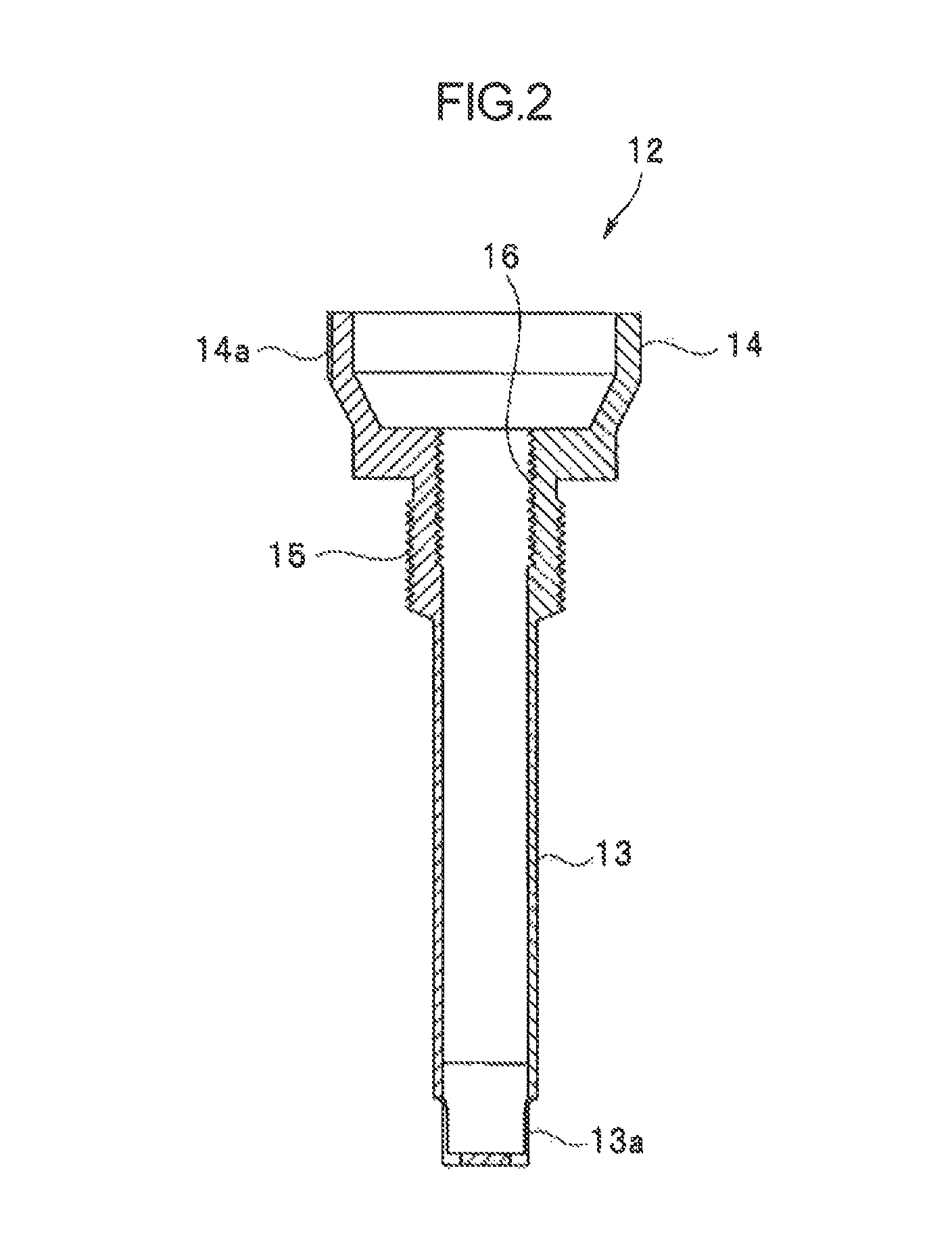
[0018]Oil within the oil pan 4 is replenished through an oil filler neck 5 that is provided on the upper side of the oil pan 4. The amount of oil in the oil pan 4 can be easily checked visually using an oil level display device 10 that is fitted to the oil filler neck 5. The configuration of the ...


PUM


Abstract

An oil level display device is fitted such that a float guide accommodating a float is attached to an oil filler neck and is plugged with a float cap. To check the amount of oil, the float cap is removed and the position of the float is checked. If a sufficient amount of oil is stored, an upward force derived from oil buoyancy is larger than a downward force of the own weight of the float, from among the forces that act on the float. The float thus protrudes beyond a large-diameter portion upon removal of the float cap from the float guide.

Description

CROSS-REFERENCE TO RELATED APPLICATIONS[0001]The present application claims priority from Japanese Patent Application No. 2013-166483 filed on Aug. 9, 2013, the entire contents of which are hereby incorporated by reference.BACKGROUND[0002]1. Technical Field[0003]The present invention relates to an oil level display device of an engine that allows visually checking an amount of oil, without insertion or removal of an oil level gauge.[0004]2. Related Art[0005]Generally, an oil level gauge is pulled out of an oil filler tube that is provided vertically on an oil pan of an engine, and the amount of lubricant oil stored in the oil pan is checked on the basis of the position of oil adhered to the gauge body at the leading end of the gauge. Such oil level gauges have a drawback in that the operator must insert and remove manually the gauge in order to check the amount of oil. In particular, when various devices are disposed around the engine, the position of the oil level gauge is at the b...

Claims


Application Information

Patent Timeline
Patent Type & Authority Patents(United States)
IPC IPC(8): F01M11/12G01F23/66F16N19/00
CPCF01M11/12G01F23/66F16N19/003G01F23/64
Inventor NOGUCHI, MASANORI
Owner SUBARU CORP
Why Eureka
Try Eureka