Alignment element for an injector, and method for manufacturing an injector

a technology of alignment element and injector, which is applied in the direction of manufacturing tools, machines/engines, mechanical equipment, etc., can solve the problems of large number of injection molds required due to the variety of engine types, unsatisfactory cost increase, and shifted level of effort for alignmen

Active Publication Date: 2017-03-07
ROBERT BOSCH GMBH
View PDF28 Cites 0 Cited by
  • Summary
  • Abstract
  • Description
  • Claims
  • Application Information

AI Technical Summary

Benefits of technology

[0003]The method according to the present invention for manufacturing an injector has the advantage that an alignment element is provided which may be easily pushed onto a part of a preassembled injection module, so that the injection module together with the alignment element may be inserted into an injection mold in an aligned manner, and the extrusion coating may be molded on in a subsequent step. The alignment element is flexible during the pushing-on operation, and is welded to the injection module with the aid of a welding step. At the same time as the welding-on operation, a stiffening of the alignment element is carried out so that the alignment element in particular withstands the subsequent injection process. For this purpose, the alignment element is essentially disk-shaped and has at least one slot. The slot provides the flexibility during the pushing-on operation. In the subsequent welding step the slot is welded shut at the same time as the alignment element is welded onto the injection module, so that the rigidity of the alignment element which is then necessary for the injection process is present. Thus, the present invention elegantly achieves the aim that on the one hand it should be easy to push on the alignment element, which requires a reduced rigidity, and on the other hand the alignment element should be as rigid as possible for the injection process in order to avoid deformation due to a high injection pressure, and thus a misalignment in the injection mold. The alignment element which is stiffened by the welding operation in particular prevents a deformation from occurring during the injection process in such a way that the alignment element comes into contact with a wall area of the injection mold, so that it would be externally visible in the finished injector. As a result, however, the injector would no longer be leak-tight against spray water. However, according to the present invention a stiffening of the alignment element is carried out at the same time as the welding-on process of the alignment element to the preferably tubular part of the injection module, so that the alignment element may be simultaneously fastened to the injection module and stiffened in one step.
[0004]For the welding-on step, the injection module together with the alignment element which is pushed onto same are particularly preferably rotated. A particularly simple welding step may be carried out in this way.
[0005]According to another preferred embodiment of the present invention, a welding plane in which the alignment element is welded to the injection module does not coincide with a welding plane in which the slot is welded shut. This allows greater freedom of design of the alignment element without thus impairing the quality of the weld seam for fixing the alignment element to the injection module.

Problems solved by technology

However, since the spray pattern has effects on the fuel consumption and exhaust gas emissions, the injector in recent engines must be very precisely aligned.
However, this results in an undesirable cost increase.
This would also have the same disadvantages as the flat polished surfaces described above, and the level of effort for the alignment is shifted to the alignment operation during installation of the additional component.
The plug-in connection could also be used here as an alignment element for the injector, but the large number of injection molds required due to the variety of engine types is likewise disadvantageous.
As a result, however, the injector would no longer be leak-tight against spray water.

Method used


Image

  • Alignment element for an injector, and method for manufacturing an injector
  • Alignment element for an injector, and method for manufacturing an injector
  • Alignment element for an injector, and method for manufacturing an injector

Examples


Embodiment Construction

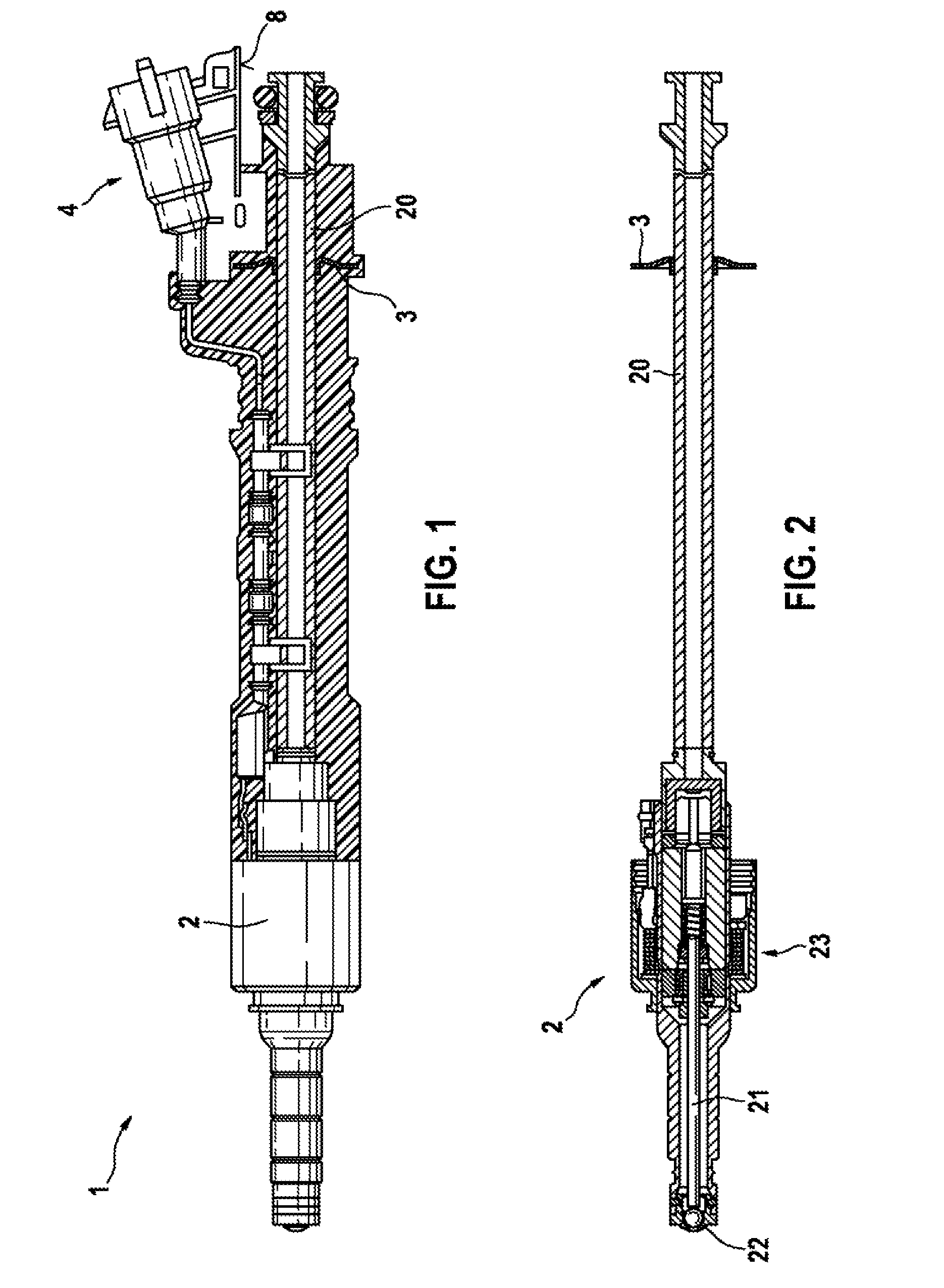
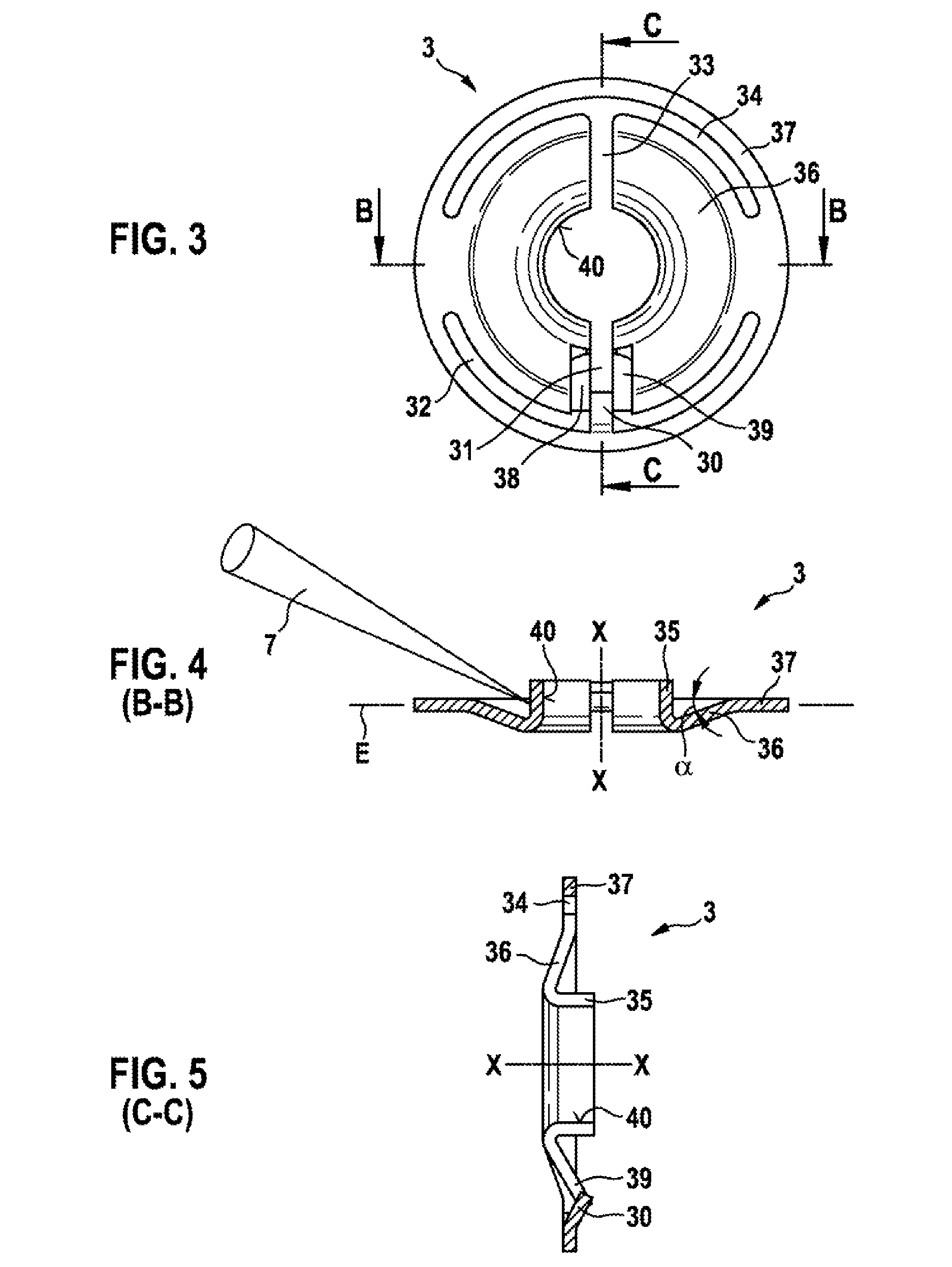
[0034]An injector having a first alignment element 3 according to the present invention as well as a method for manufacturing the injector are described in greater detail below, with reference to FIGS. 1 through 8.

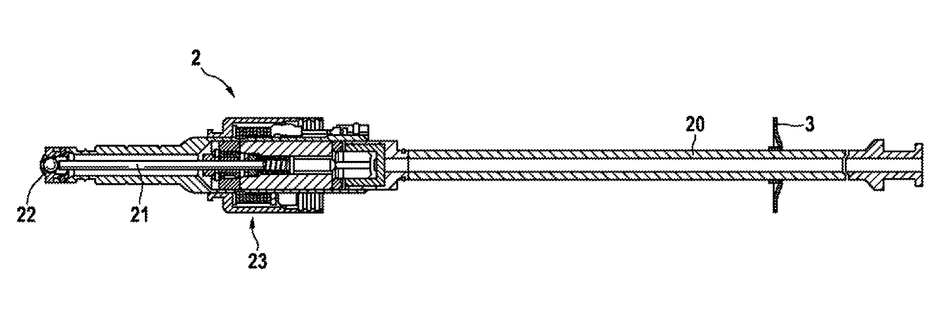
[0035]As is apparent from FIG. 1, injector 1 includes an injection module 2, shown in greater detail in FIG. 2, which in the present exemplary embodiment includes a solenoid actuator 23 in order to move a valve needle 21. The valve needle opens up or closes a valve seat 22 at one end of the injector. Injector 1 also includes a plug molding 4 (extrusion coating) which is molded onto injection module 2 shown in FIG. 2. Injection module 2 is a preassembled module. A disk-shaped alignment element 3 is preassembled on a tubular part 20 of injection module 2. Injection module 2 is inserted into an injection mold with the aid of alignment element 3, and plug molding 4 is then molded on. Plug molding 4 has an alignment surface 8 which, the same as for the actual plug-in connection...


PUM

PropertyMeasurementUnit
angleaaaaaaaaaa
circular angleaaaaaaaaaa
flexibilityaaaaaaaaaa

Abstract

A method for manufacturing an injector having an extrusion coating, including the following steps: providing an injection module, pushing a disk-shaped alignment element onto a part of the injection module, the alignment element having a slot in order to have sufficient flexibility, welding the alignment element onto the part of the injection module, at least part of the slot also being welded shut at the same time during the welding-on step in order to stiffen the alignment element, and molding the extrusion coating onto the injection module.

Description

FIELD OF THE INVENTION[0001]The present invention relates to an alignment element for an injector and a method for manufacturing an injector having a plug molding.BACKGROUND INFORMATION[0002]Injectors are known from the related art in various embodiments. Frequently, the installation situations for injectors are different for various types of engines, in particular with regard to their alignment. However, the alignment of the injectors is important, since a different spray pattern of the injector is obtained, depending on the alignment. However, since the spray pattern has effects on the fuel consumption and exhaust gas emissions, the injector in recent engines must be very precisely aligned. One alignment option, for example, would be to provide flat polished surfaces on the injection module. However, this results in an undesirable cost increase. In addition, it may be necessary to provide a specific polished surface for each type of engine. Alternatively, an additional component h...

Claims


Application Information

Patent Timeline
Patent Type & Authority Patents(United States)
IPC IPC(8): F02M61/16F02M61/14B23K26/20F16B21/20
CPCF02M61/14B23K26/20F02M61/168F02M2200/8015F02M2200/8023F02M2200/8046F02M2200/8061F02M2200/8084F16B21/20Y10T29/49888B23K26/28
Inventor SCHEFFEL, MARTINBORMANN, AXELWIESCHOLLEK, SEBASTIAN
Owner ROBERT BOSCH GMBH
Why Eureka
Try Eureka