Magnetic toner

a technology of toner and magnetic toner, applied in the field of magnetic toner, can solve the problems of inability to obtain satisfactory image density, increase in the amount of magnetic toner, and high printing cost per sheet, so as to improve the initial transfer efficiency, reduce the contamination of a member, and improve the effect of transfer quality

Active Publication Date: 2017-03-07
CANON KK
View PDF98 Cites 27 Cited by
  • Summary
  • Abstract
  • Description
  • Claims
  • Application Information

AI Technical Summary

Benefits of technology

[0029]According to one embodiment of the present invention, it is possible to impart excellent transfer property through long-term use while suppressing the contamination of a member by improving initial transfer efficiency, and suppressing the burial and separation of the external additives due to the degradation in durability.
[0030]Further features of the present invention will become apparent from the following description of exemplary embodiments with reference to the attached drawings.

Problems solved by technology

However, the external additive having a small particle diameter involves a problem in that when the magnetic toner is transferred onto a medium, a great amount of a transfer residual toner remains on a drum (electrophotographic photosensitive member), and hence the consumption amount of the magnetic toner increases in order to satisfy image density, with the result that printing cost per sheet becomes high.
As a result, the transfer property is deteriorated during long-term use, which may cause image quality defects, with the result that there is a concern that satisfactory image density may not be obtained, and the consumption amount of the magnetic toner may increase further compared to that of the initial stage.
However, when a toner using the monodispersed spherical external additive is applied to the magnetic one-component jumping development method, although the toner consumption amount is suppressed by the improvement of initial transfer efficiency, there is a possibility that the transfer property is deteriorated during long-term use, which may cause image quality defects.
However, this procedure is not necessarily effective for a pulverized toner, and the inorganic fine powder is rolled to a recess of the toner particle due to the strong shear force in the gap between the rotation drive part and the casing, with the result that there is a possibility that the inorganic fine powder may not serve as an external additive sufficiently.
As a result, the developing property and transfer property are degraded, and there is a possibility that problems such as a white streak and density unevenness may occur.

Method used


Image

  • Magnetic toner
  • Magnetic toner
  • Magnetic toner

Examples


example 1

[0252]1.1 parts of the organic-inorganic composite fine particles 1 serving as a first external additive and 0.5 part of the inorganic particles 3 serving as a second external additive were externally added to and mixed with 100 parts of the magnetic toner particles 1 with a Henschel mixer, and the mixture was sifted through a mesh having an opening of 100 μm to obtain a negatively triboelectrically chargeable magnetic toner 1. Table 4 shows various physical properties of the obtained magnetic toner 1.

[0253][Evaluation Items]

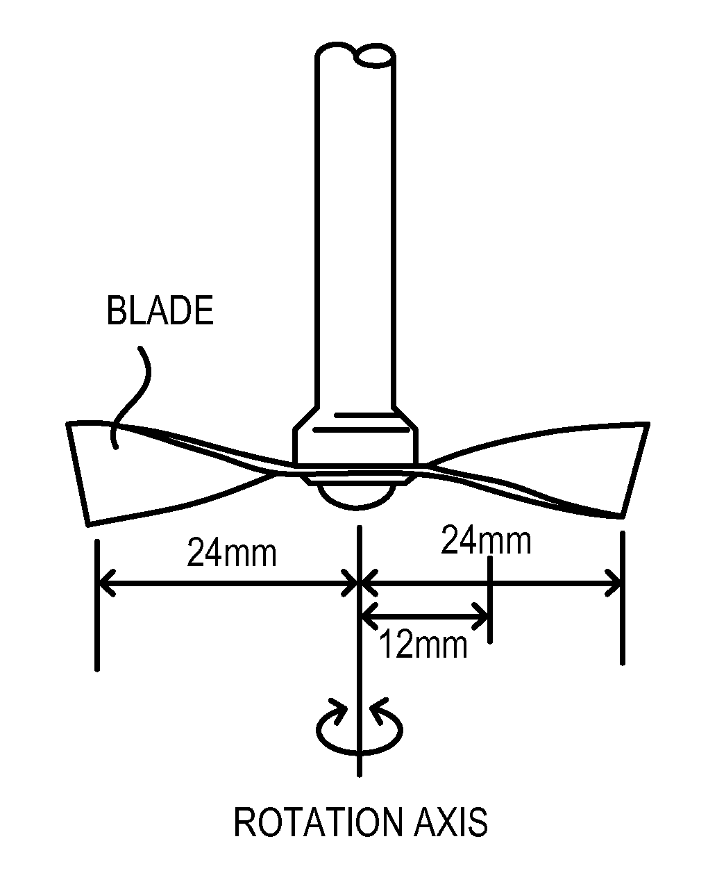
[0254]HP LaserJet Enterprise600 M603dn was remodeled to a process speed of 400 mm / s to be used, considering the further increase in speed and increase in life of a printer in the future.

[0255]A predetermined process cartridge was filled with 982 g of the magnetic toner 1. An image-forming test of 42,000 sheets in total was conducted in a mode set so that a subsequent job starts after a machine once stops between jobs, with one job being two sheets of a horizonta...

examples 2 to 11

[0284]Magnetic toners 2 to 11 were obtained in the same way as in the production example of the magnetic toner 1 except that the magnetic toner particles, the first external additive, the second external additive, and parts by mass were changed. Table 4 shows various physical properties of the obtained magnetic toners. Further, Table 5 shows results obtained by performing evaluation in the same way as in Example 1.


PUM

PropertyMeasurementUnit
number-average particle diameteraaaaaaaaaa

Abstract

Provided is a magnetic toner in which enhancement of initial transfer efficiency and transfer efficiency that is stable during a long-term use are achieved by simultaneously suppressing the friction force between the toner and a drum and the cohesion between toners, and further the degradation in chargeability and fluidity caused by the deterioration of the toner. The magnetic toner includes: a magnetic toner particle; a first external additive; and a second external additive. The first external additive includes an organic-inorganic composite fine particle, a plurality of convexes derived from an inorganic fine particle being present on a surface of the organic-inorganic composite fine particle, and has a number-average particle diameter of 50 nm or more and 500 nm or less. The second external additive includes a silica fine particle and has a number-average particle diameter of 5 nm or more and 30 nm or less. A shear load calculated from a rotation torque is 0.50 kPa or more and 2.00 kPa or less when a disc-shaped disc is pressed against a surface of a magnetic toner powder layer, the magnetic toner powder layer being produced by applying a vertical load of 9.0 kPa to the magnetic toner, under a vertical load of 5.0 kPa, and the disc which is being pressed is rotated, and an absolute value |ζ(T)−ζ(A1)| of a difference between a zeta potential ζ(T) of the magnetic toner particle dispersed in water and a zeta potential ζ(A1) of the first external additive dispersed in water is 50 mV or less.

Description

TECHNICAL FIELD[0001]The present invention relates to a magnetic toner to be used in an electrophotographic method, an image forming method for visualizing an electrostatic image, and a toner jet method (hereinafter sometimes referred to simply as “magnetic toner”).BACKGROUND ART[0002]Hitherto, a magnetic toner to be used for forming an image by a magnetic one-component jumping development method has been required to have high fluidity so as to achieve stable supply to a developing sleeve, image density, and image stabilization, and as an external additive for imparting the fluidity, an external additive having a small particle diameter has been frequently used. However, the external additive having a small particle diameter involves a problem in that when the magnetic toner is transferred onto a medium, a great amount of a transfer residual toner remains on a drum (electrophotographic photosensitive member), and hence the consumption amount of the magnetic toner increases in order ...

Claims


Application Information

Patent Timeline
Patent Type & Authority Patents(United States)
IPC IPC(8): G03G9/08G03G9/087G03G9/097G03G9/083
CPCG03G9/0839G03G9/081G03G9/083G03G9/0819G03G9/0827G03G9/0833G03G9/08755G03G9/09716G03G9/09725
Inventor TSUDA, SHOHEINISHIKAWA, KOJIYAMAZAKI, KATSUHISAHOTTA, YOJIROTERAUCHI, KAZUOSHIOZAWA, MOTOHIDENAKA, TAKESHIMIZUGUCHI, TAKUYAITAKURA, TAKAYUKI
Owner CANON KK
Why Eureka
Try Eureka