Liquid crystal display panel with fluid control wall

A liquid crystal display panel, flow control technology, applied in nonlinear optics, instruments, optics, etc., can solve problems such as defective, liquid crystal pollution display, etc.

Inactive Publication Date: 2004-08-25
HITACHI DISPLAYS
View PDF4 Cites 26 Cited by
  • Summary
  • Abstract
  • Description
  • Claims
  • Application Information

AI Technical Summary

Problems solved by technology

Accordingly, there is a possibility that display de

Method used


Image

  • Liquid crystal display panel with fluid control wall
  • Liquid crystal display panel with fluid control wall
  • Liquid crystal display panel with fluid control wall

Examples


Embodiment Construction

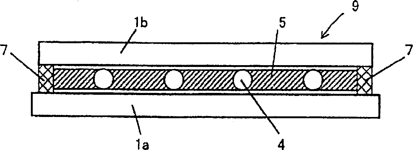
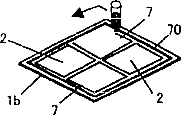
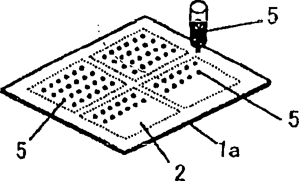
[0065] Hereinafter, embodiments of the liquid crystal display panel according to the present invention will be described in detail with reference to the accompanying drawings. 6A-6C are explanatory views of a first embodiment of a liquid crystal display panel according to the present invention. FIG. 6A is a perspective view of a TFT substrate, which is shown as an example of a case where four liquid crystal display panels are produced from a large-sized substrate 1 . Fig. 6B is a top view showing one sheet of the liquid crystal display panel shown in enlarged Fig. 6A, Figure 6C It is a cross-sectional view along line A-A of FIG. 6B.

[0066] FIG. 6A shows the positional relationship between the display area 2 of the four liquid crystal display panels 9, the sealing material 7, and the flow control wall 3. FIG. Each liquid crystal display panel 9 such as Figure 6C As shown, liquid crystal 5 is sandwiched between a pair of substrates, TFT substrate 1a and CF substrate 1b, a...


PUM


Abstract

A substrate includes fluid control walls for controlling the liquid crystal fluid closer to the liquid crystal dropped spot of a display area or frame-like fluid control walls between a sealing material and the display area. After the liquid crystal is dropped on the display area, a pair of substrates are pasted and then picked out in the atmosphere for applying pressure onto the pair of substrates and diffusing the liquid crystal. The liquid crystal fluid control walls serve to control the liquid crystal fluid, thereby suppressing the liquid crystal contamination caused by the contact of the unhardened sealing material with the liquid crystal and the relevant display failure.

Description

technical field [0001] The invention relates to a liquid crystal display panel manufactured by liquid crystal drop injection method. technical background [0002] Liquid crystal display devices have been widely used as thin, light-weight and low-power-consumption display devices. A liquid crystal display device is constituted by incorporating a drive circuit and the like into a flat-panel device called a liquid crystal display panel. figure 1 It is a schematic cross-sectional view for explaining the schematic structure of one liquid crystal display panel. LCD panel 9 such as figure 1 As shown, the structure is such that the liquid crystal 5 is sandwiched between a pair of substrates that are one of the substrates forming a thin film transistor (Thin Film Transistor: TFT, hereinafter referred to as TFT) (hereinafter also referred to as TFT). TFT substrate) 1a, and the other substrate (color filter substrate, hereinafter also referred to as CF substrate) on which red (R), g...

Claims


Application Information

Patent Timeline
IPC IPC(8): G02F1/1339G02F1/1341
CPCG02F1/1341G02F1/1339
Inventor 川邊俊一朴木秀行東人士新井好宏小林節郎
Owner HITACHI DISPLAYS
Why Eureka
Try Eureka