Vehicle-mounted antenna device

a technology of antenna device and vehicle, which is applied in the direction of resonant antenna, printed circuit non-printed electric component association, electric apparatus casing/cabinet/drawer, etc., can solve the problems of loss in transmission cable, increased transmission loss, and increased transmission loss, so as to reduce the performance of circuit section the effect of performance degradation

Active Publication Date: 2017-03-07
DENSO CORP
View PDF11 Cites 0 Cited by
  • Summary
  • Abstract
  • Description
  • Claims
  • Application Information

AI Technical Summary

Benefits of technology

[0005]In antenna devices, as frequencies of radio waves to be used become higher, loss in a transmission cable, i.e., transmission loss becomes more significant. In particular, an antenna device used for vehicle-to-vehicle communication and vehicle-to-road-side communication uses radio waves of a high frequency of 5.9 GHz band to be used become higher, and therefore the transmission loss becomes significant. In this case, both the board having the antenna element section and at least part of a wireless communication circuit capable of performing wireless communication with an external device may be placed in the space formed by the housing and the base. When the antenna element section and the circuit section are placed in the same space, the circuit section is located close to the antenna element section, so that the transmission loss can be reduced.

Problems solved by technology

In antenna devices, as frequencies of radio waves to be used become higher, loss in a transmission cable, i.e., transmission loss becomes more significant.
In particular, an antenna device used for vehicle-to-vehicle communication and vehicle-to-road-side communication uses radio waves of a high frequency of 5.9 GHz band to be used become higher, and therefore the transmission loss becomes significant.
Since the heat stays in the space, a temperature of the circuit section increases, and performance of the circuit section may be degraded.
However, forming a vent or adding a cooling fan is undesirable from a design perspective because the housing is sealed and part of the outer shape of the vehicle.

Method used


Image

  • Vehicle-mounted antenna device
  • Vehicle-mounted antenna device
  • Vehicle-mounted antenna device

Examples


first embodiment

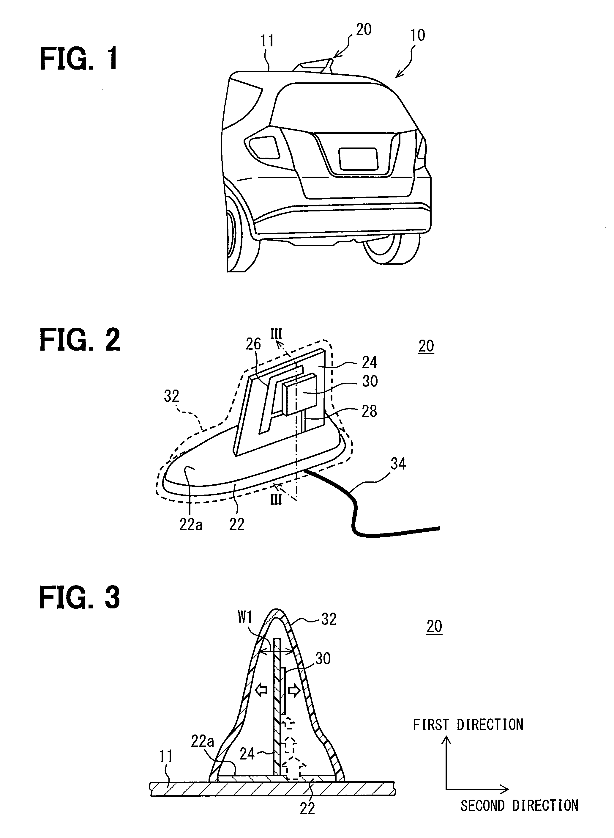
[0027]As shown in FIG. 1, a vehicle-mounted antenna device 20 according to the present embodiment is mounted on a roof 11 of a vehicle 10. The vehicle-mounted antenna device 20 is what is called a shark fin antenna device. The vehicle-mounted antenna device 20 is hereinafter simply referred to as the antenna device 20.

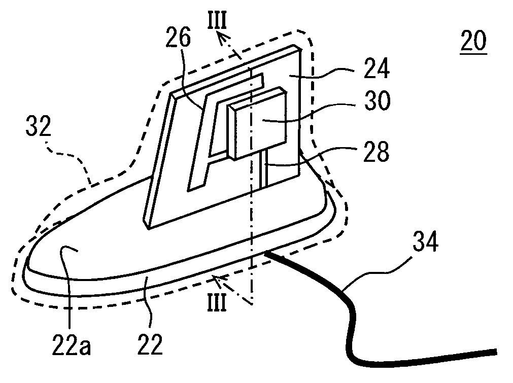
[0028]As shown in FIGS. 2 and 3, the antenna device 20 mainly includes a base 22, a board 24 having an antenna element section 26, a circuit section 30 serving as at least part of a wireless communication circuit, and a housing 32 made of a resin material and forming a projection of a vehicle outer shape.

[0029]The base 22 is used to fix the board 24 to the vehicle 10 and mounted on the roof 11 through a mounting member which is not shown. The base 22 has a flat plate shape and is mounted almost parallel to the roof 11. Further, when the base 22 is made of a metal material and electrically connected to the roof 11 through the mounting member, the base 22 serves as a gro...

second embodiment

[0045]Descriptions of the same structures of the present embodiment as those of the antenna device 20 of the above-described embodiment are omitted.

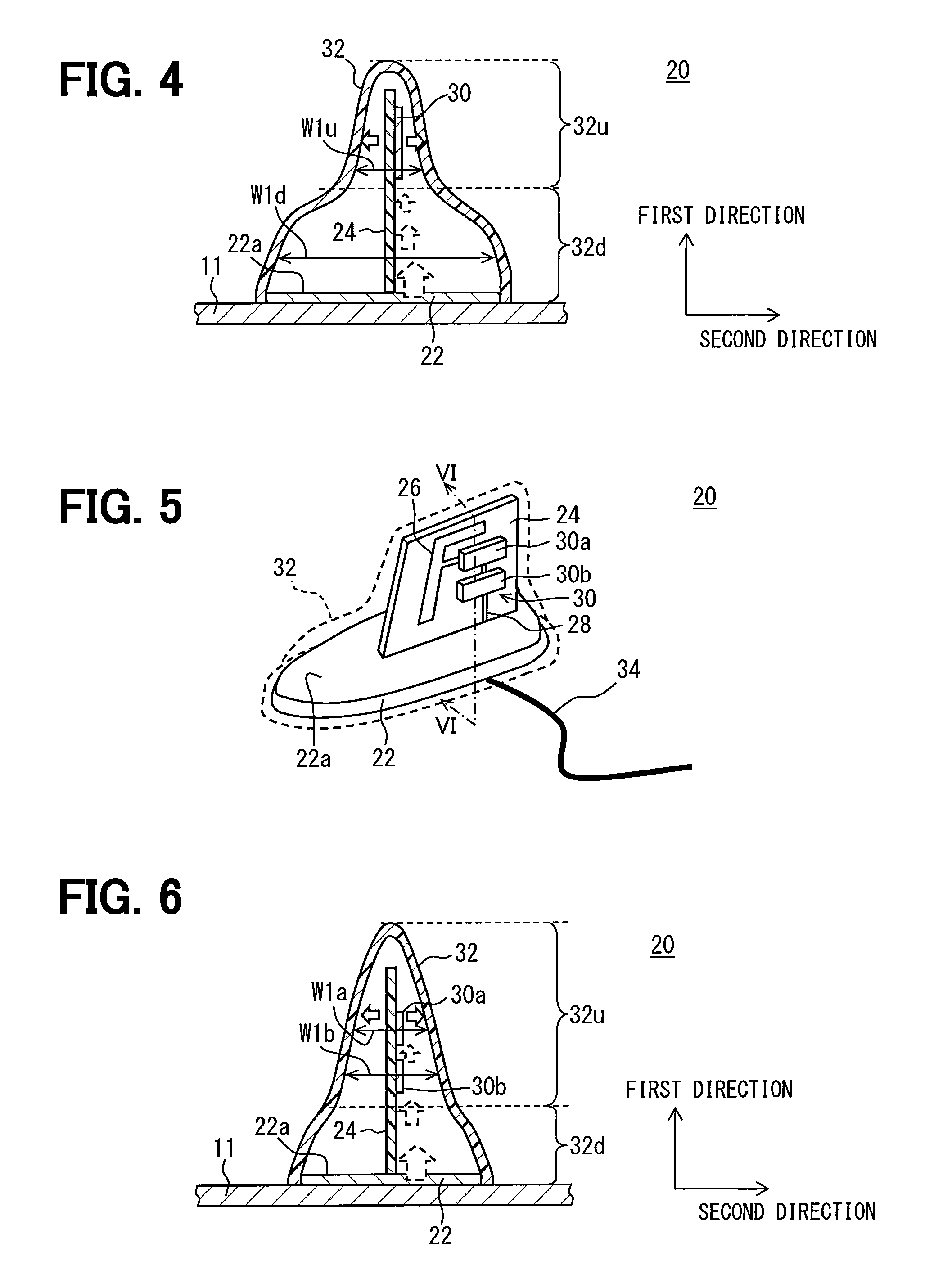
[0046]As exemplified in FIG. 4, according to the present embodiment, the first direction and the second direction are almost perpendicular to each other. The housing 32 has a lower part 32d and an upper part 32u. The lower part 32d extends from an end of the housing 32 on the base 22 side to a predetermined height in the first direction. The upper part 32u is located further away from the base 22 than the lower part 32d. The opening width W1 is set so that a minimum value of an opening width W1d of the lower part 32d in the second direction can be greater than a maximum value of an opening width W1u of the upper part 32u in the second direction. That is, the opening width W1 is smaller in the upper part 32u than in the lower part 32d. The circuit section 30 is located in the upper part 32u. The other aspects are the same as those of the ...

third embodiment

[0051]Descriptions of the same structures of the present embodiment as those of the antenna device 20 of the above-described embodiment are omitted.

[0052]As exemplified in FIGS. 5 and 6, according to the present embodiment, the circuit section 30 includes two components 30a and 30b which are independent of each other. When operating, the first component 30a generates more heat than the second component 30b. They are implemented on the board 24 so that the first component 30a can be located further away from the base 22 than the second component 30b in the first direction. In an example shown in FIGS. 5 and 6, the first component 30a has a RF circuit including a power amplifier, and the second component 30b has a baseband circuit.

[0053]In such an approach, as indicated by a broken arrow in FIG. 6, heat radiated from the sun and transferred through the base 22 from the roof 11 to the first component 30a can be made smaller than heat radiated from the sun and transferred to the second ...


PUM


Abstract

A vehicle-mounted antenna device includes a base, a board, a circuit section, and a housing. The base is mountable on a roof of a vehicle. The board has an antenna element section and is stood on a surface of the base. The circuit section serves as at least part of a wireless communication circuit electrically connected to the antenna element section. The housing is made of a resin material and forms a projection of a vehicle outer shape. The board and the circuit section are located in space formed by the base and the housing. The board is stood on the surface of the base so that a first direction perpendicular to the surface of the base differs from a second direction equal to a thickness direction of the board. The circuit section implemented on the board at a position away from the base in the first direction.

Description

CROSS REFERENCE TO RELATED APPLICATIONS[0001]This application is a U.S. National Phase Application under 35 U.S.C. 371 of International Application No. PCT / JP2013 / 003858 filed on Jun. 20, 2013 and published in Japanese as WO 2014 / 033994 A1 on Mar. 6, 2014. This application is based on and claims the benefit of priority from Japanese Patent Application No. 2012-193250 filed on Sep. 3, 2012. The entire disclosures of all of the above applications are incorporated herein by reference.TECHNICAL FIELD[0002]The present disclosure relates to vehicle-mounted antenna devices and in particular, relates to a vehicle-mounted antenna device used for vehicle-to-vehicle communication and vehicle-to-road-side communication.BACKGROUND ART[0003]As disclosed in a patent literature 1, an antenna device is known that has a GPS antenna, a DTV antenna, and a radio antenna which are placed in space formed by an antenna base (hereinafter referred to as a base) and an antenna cover (hereinafter referred to a...

Claims


Application Information

Patent Timeline
Patent Type & Authority Patents(United States)
IPC IPC(8): H01Q1/32H01Q1/02H01Q1/42H01Q1/24H01Q9/42H05K5/00H05K1/18
CPCH01Q1/3275H01Q1/02H01Q1/241H01Q1/42H01Q9/42H05K1/181H05K5/003H05K2201/10098H05K2201/10507
Inventor YUKIZAKI, YASUMUNESUZUKI, TADAOKATAOKA, RYOHEISUGIMOTO, YUJI
Owner DENSO CORP
Why Eureka
Try Eureka